
HVAC with detached deflector

a deflector and hvac technology, applied in the field of airflow control in heating and air conditioning units, can solve the problems of large housing space needed in such systems, and the need for much greater space within the vehicle itself in order to carry hvac, so as to reduce the vibration of the deflector, reduce the amount of heat pickup, and reduce the effect of vibration

Active Publication Date: 2008-08-05
VALEO CLIMATE CONTROL
View PDF9 Cites 25 Cited by
  • Summary
  • Abstract
  • Description
  • Claims
  • Application Information

AI Technical Summary

Benefits of technology

This solution allows for efficient air distribution and temperature control in a smaller space, reducing the overall cost and complexity of the system while effectively managing water drainage and air recirculation.

Problems solved by technology

A large housing space was thus needed in such systems.
In order to mold a deflector directly into the housing, however, a much greater space is required within the vehicle itself in order to carry the HVAC.

Method used


Image

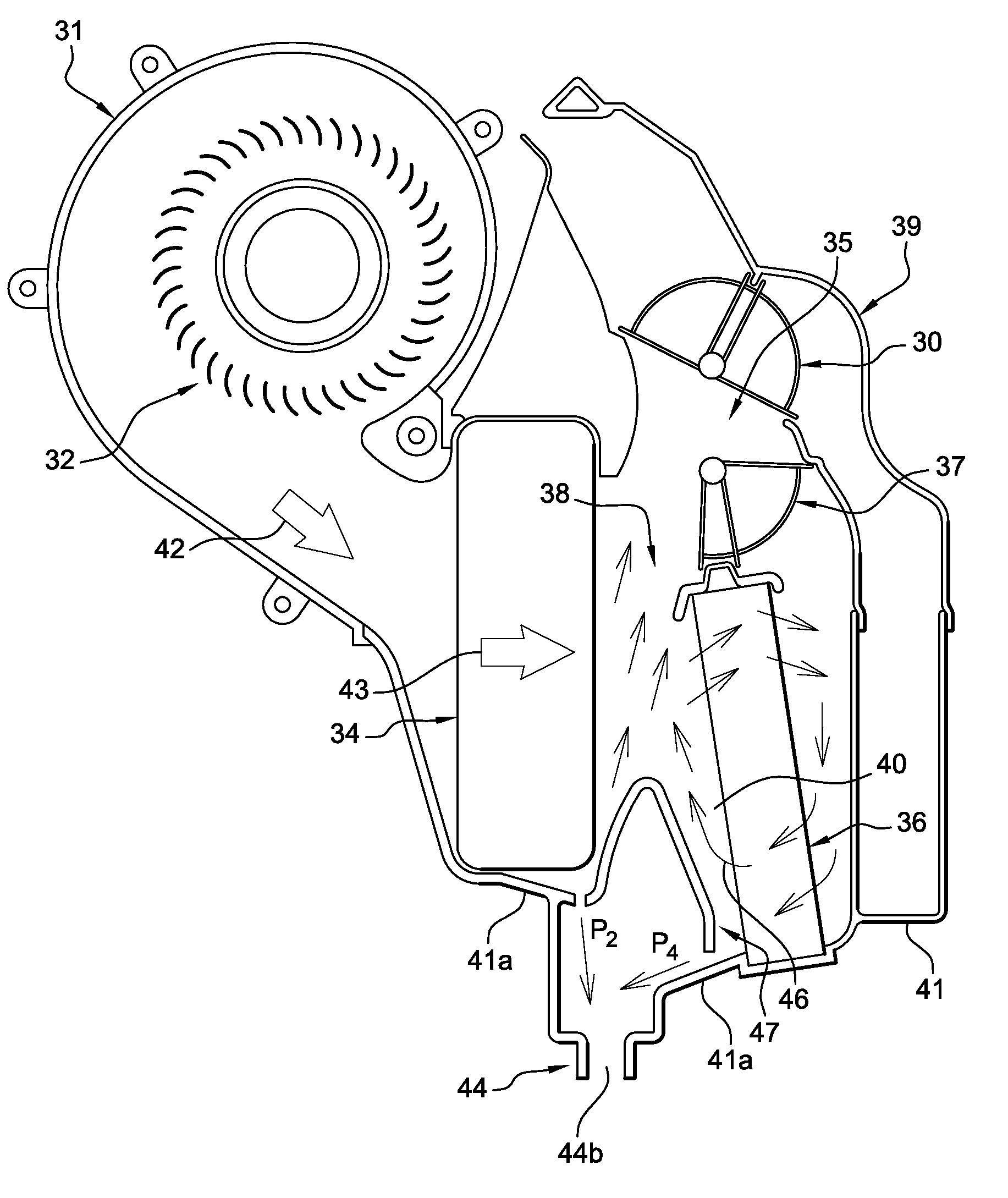
  • HVAC with detached deflector
  • HVAC with detached deflector
  • HVAC with detached deflector

Examples


Embodiment Construction

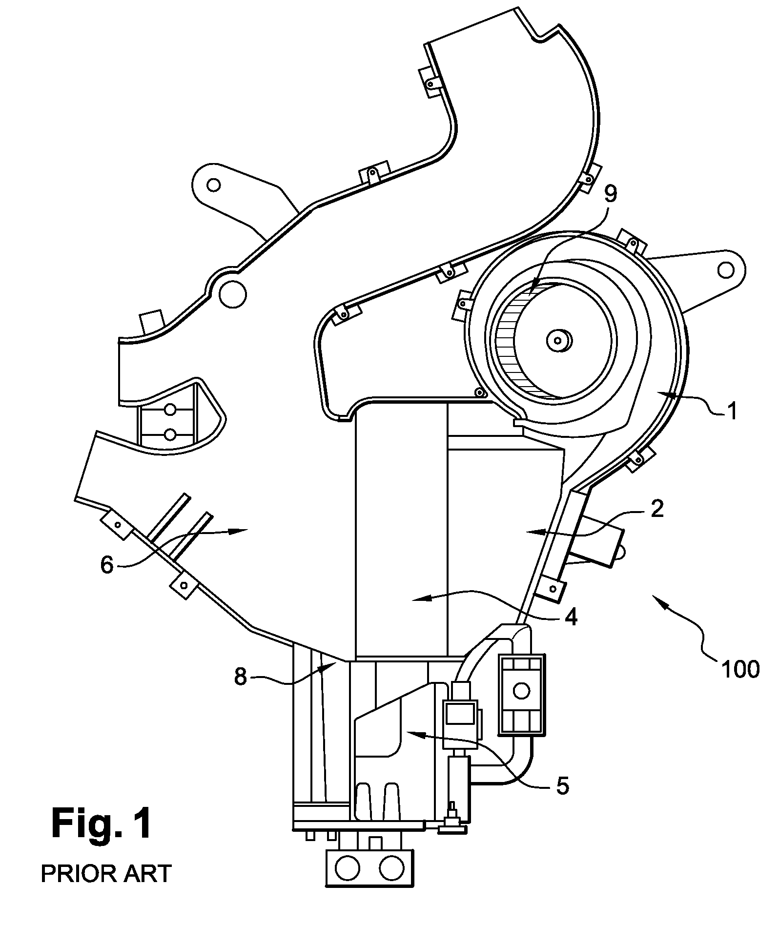
[0036]A prior art HVAC system is shown in FIG. 1. The HVAC system or assembly (100) core has upper (2) and lower (8) housings. Ambient outside air or recirculated interior air is directed through air-conditioning evaporator (4) by the HVAC blower (9) in air blower scroll housing (1). After the air exits from evaporator (4), part of the air is directed through lower housing (8) and heater core (6)

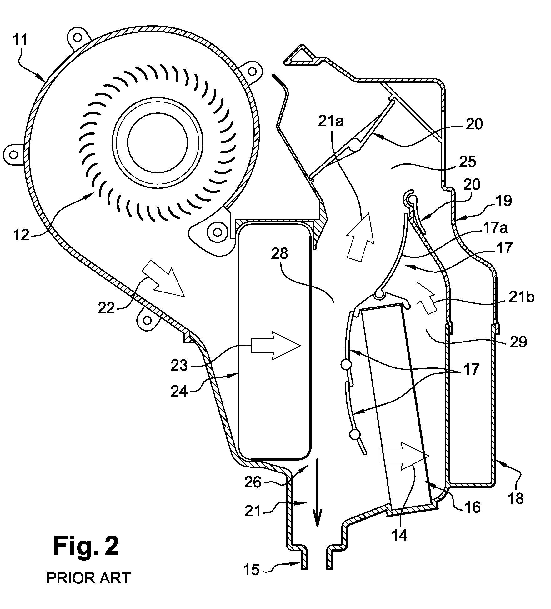
[0037]In prior art drawing FIG. 2, air from blower wheel (12) creates an air path (22) directed towards the evaporator (24). Cold air is found in cold air path (23), and the cooling of air allows condensate to form which follows condensate path (26) to drain tube (15). Blend doors (17) direct air and allow various amounts of air to enter into hot air path (14) through heater core (16). Cold air follows path (21a) to distribution area (25), and heated air follows path (21b) to distribution area (25), after passing through additional blend door (17a). Air can be distributed (25) to outlets (no...


PUM


Abstract

A structure to provide air flow an mixture in an HVAC unit utilizing a separate piece air deflector located within the lower housing of the HVAC unit and ribs to direct airflow, the separate piece air deflector configured to cause air deflection and airflow towards the distribution area of the unit.

Description

BACKGROUND OF THE INVENTION[0001]The present invention relates to the field of directing ventilating air and airflow control in a ventilating, heating or air conditioning system. More specifically, the present invention relates to a structure and method to provide air flow diversion via a detached air deflector within the HVAC housing.[0002]1. Field of the Invention[0003]The present invention relates generally to airflow control in heating and air conditioning units, particularly for automotive purposes.[0004]2. Description of the Prior Art[0005]In automotive ventilating systems and in ventilating systems in general, air needs to be directed within the HVAC unit to provide for the correct air volumes and temperatures to desired areas prior to its flow through respective air passageways. The air can be directed via outlet means such as doors, and, specifically, blend doors, so the air proceeds to the desired area under selected design conditions. For example, a design may provide for...

Claims


Application Information

Patent Timeline
Patent Type & Authority Patents(United States)
IPC IPC(8): B60H1/00F25D21/14
CPCB60H1/00028B60H1/3233B60H2001/00092
Inventor NEWMAN, DAVID S.DELPLACE, RICHARD E.MARSHALL, STEVEN B.
Owner VALEO CLIMATE CONTROL
Learn More