
Apparatus and method for controlling velocity of motor

a technology of motor and actuator, which is applied in the direction of electrical apparatus, control system, electronic commutator, etc., can solve the problems of limiting the installation environment of the apparatus, difficult or impossible to estimate the rotational velocity of the motor in a zero-speed or low-speed period, and high resolution of the position sensor

Inactive Publication Date: 2008-07-29
SAMSUNG ELECTRONICS CO LTD
View PDF19 Cites 5 Cited by
  • Summary
  • Abstract
  • Description
  • Claims
  • Application Information

AI Technical Summary

Benefits of technology

This approach enables accurate and stable motor velocity control throughout the entire speed range, including initial start-up and high-speed operations, while reducing the impact of disturbance torque fluctuations, thereby improving system reliability and performance.

Problems solved by technology

However, the position sensor having a high resolution is expensive, and restricts an installation environment of an apparatus for controlling the motor.
However, a problem arises in that it is difficult or impossible to estimate the rotation velocity of the motor in a zero-speed or a low-speed period of the motor because the rotation velocity of the motor is estimated by the inverse electromotive force or by estimating a magnetic flux of the rotor.
However, if the sensorless control method and apparatus disclosed in U.S. Pat. No. 6,081,093 is applied to a system in which a fluctuation of disturbance torque is great in an initial start period, such as that of a washing machine, the system may fail to initially start because of an instability operating caused by a large error in a real position of the rotor and a position command, and between the velocity and the velocity command.

Method used


Image

  • Apparatus and method for controlling velocity of motor
  • Apparatus and method for controlling velocity of motor
  • Apparatus and method for controlling velocity of motor

Examples


Embodiment Construction

[0038]Reference will now be made in detail to the exemplary embodiments of the present invention, examples of which are illustrated in the accompanying drawings, wherein like reference numerals refer to like elements throughout.

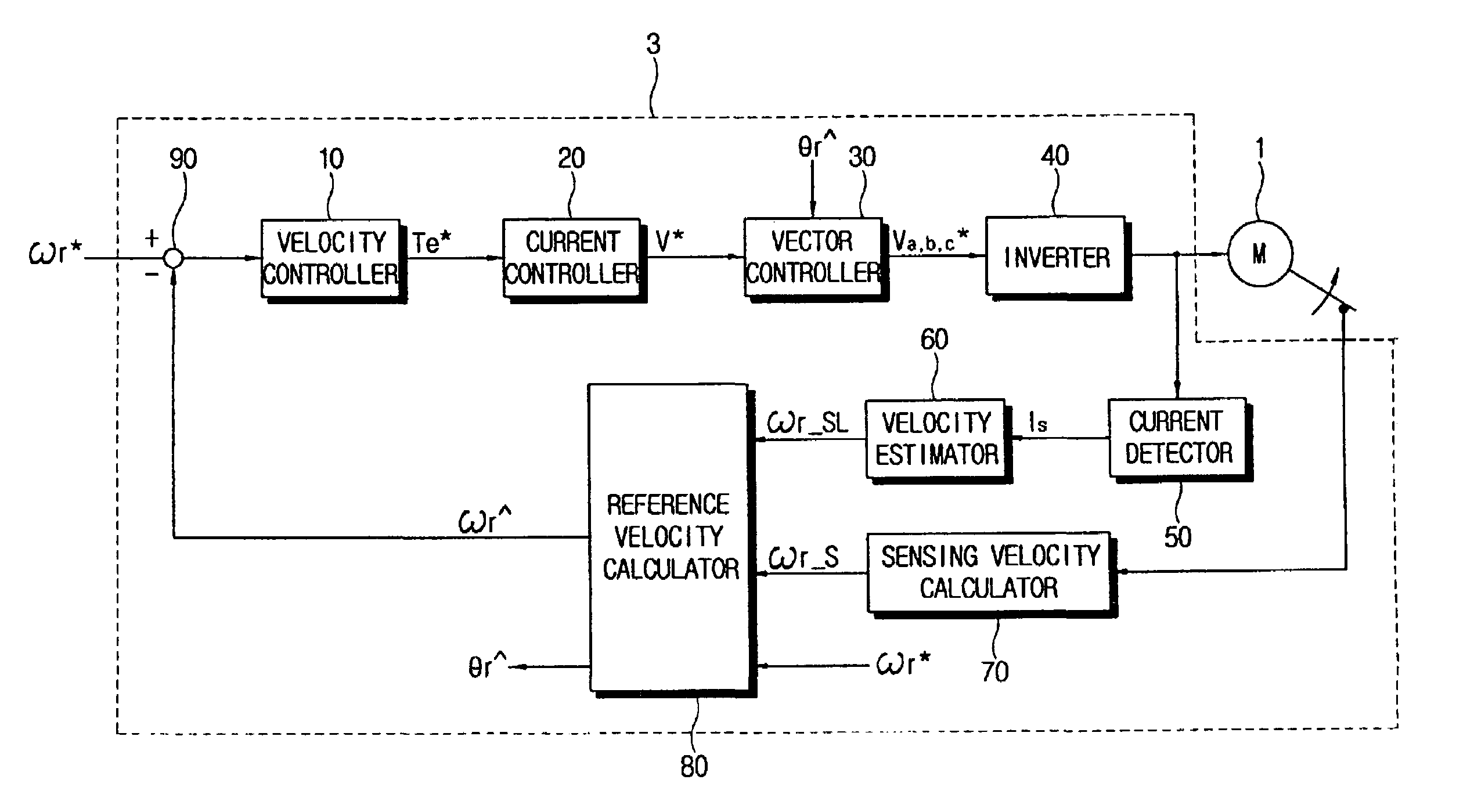
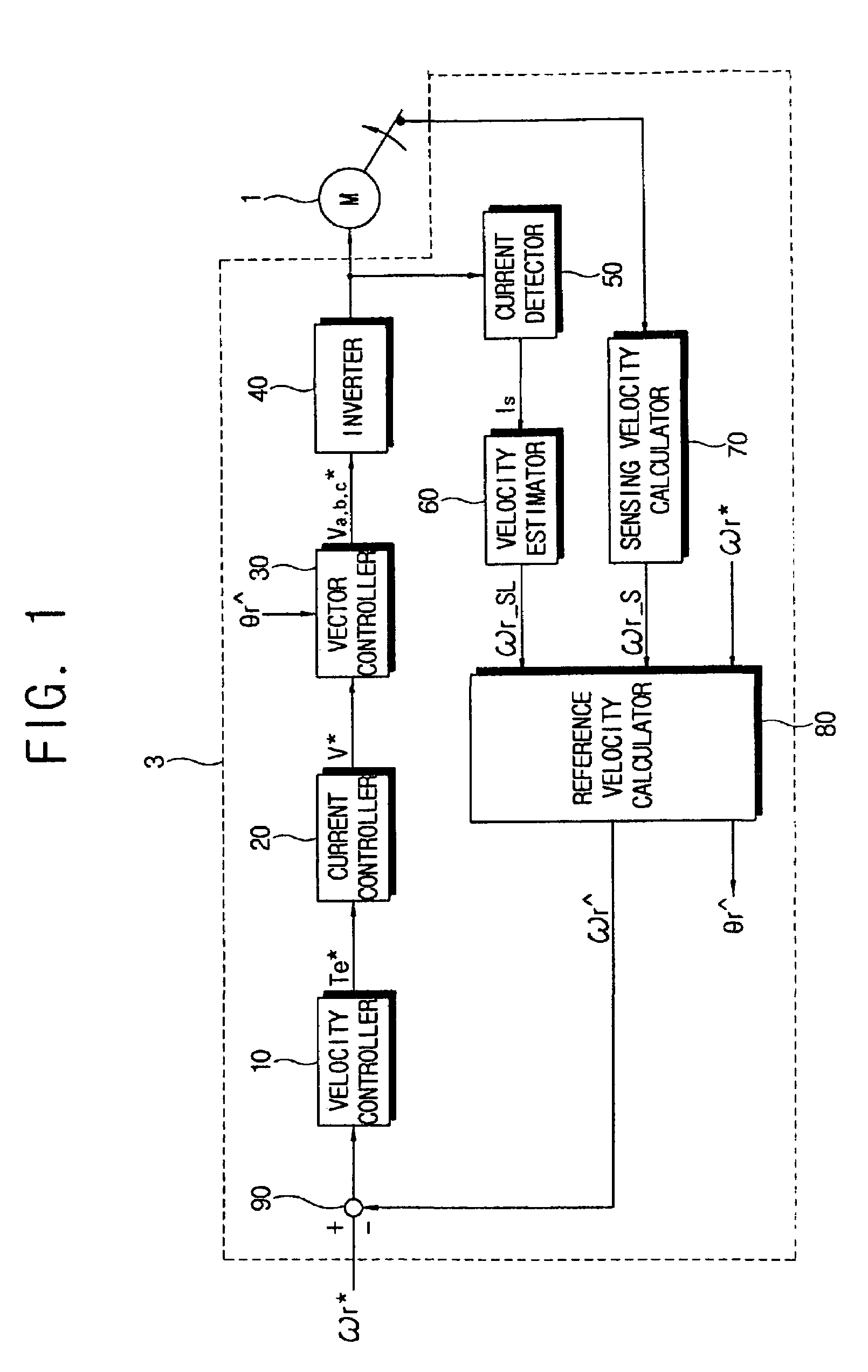
[0039]As shown in FIG. 1, an apparatus 3 for controlling a velocity of a motor 1 according to an exemplary embodiment of the present invention comprises an inverter 40, a current detector 50, a velocity estimator 60, a sensing velocity calculator 70, a reference velocity calculator 80, a velocity controller 10, a current controller 20, and a vector controller 30.

[0040]The motor 1 controlled by the apparatus 3 according to the exemplary embodiment of the present invention may comprise at least one of a surface-mounted permanent magnet synchronous motor (SPMSM) and an interior permanent magnet synchronous motor (IPMSM). The motor 1 operates according to power supplied from the inverter 40.

[0041]The inverter 40 supplies the power to the motor 1 for operating. Th...


PUM


Abstract

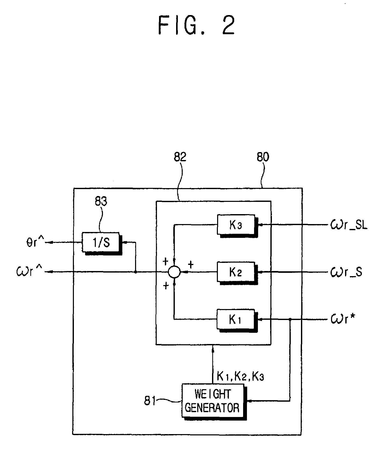
An apparatus controlling a velocity of a motor having a rotor, includes a sensing velocity calculator sensing a rotation velocity of the motor, and calculating a sensing velocity on the basis of the sensed rotation velocity of the motor; a velocity estimator estimating an estimation velocity of the motor based on an information about a position error of the rotor; and a reference velocity calculator dividing an overall velocity period of the motor into a plurality of unit velocity periods based on a command velocity for controlling the rotation velocity of the motor, calculating a sum of the sensing velocity, the estimation velocity, and the command velocity after multiplying at least one of the sensing velocity, the estimation velocity, and the command velocity by a predetermined weight, and outputting the sum as a reference estimation velocity of the motor.

Description

CROSS-REFERENCE TO RELATED APPLICATIONS[0001]This application claims priority from Korean Patent Application No. 10-2004-0103251, filed on Dec. 8, 2004, in the Korean Intellectual Property Office, the disclosure of which is incorporated herein by reference.BACKGROUND OF THE INVENTION[0002]1. Field of the Invention[0003]Apparatuses and methods consistent with the present invention relate to controlling a velocity of a motor, and more particularly, to controlling a velocity of a motor by calculating an accurate reference estimation velocity of the motor in an overall velocity period of the motor.[0004]2. Description of the Related Art[0005]Generally, a vector control method for calculating an accurate rotation velocity of a motor is broadly used in industry fields requiring high performance of the motor. In the vector control method, a position sensor having a high resolution, such as an optical encoder and a resolver, is used because the vector control method requires continuously se...

Claims


Application Information

Patent Timeline
Patent Type & Authority Patents(United States)
IPC IPC(8): H02P27/04
CPCH02P23/14H02P6/18
Inventor KIM, HYUN-BAE
Owner SAMSUNG ELECTRONICS CO LTD
Learn More