
Method and device for regulating the drive torque following a load change in hybrid vehicles

a technology of hybrid vehicles and drive torque, which is applied in hybrid vehicles, tractors, instruments, etc., can solve the problems of reduced cornering stability of motor vehicles, motor vehicles become unstable, driven wheels exhibit brake slippage, etc., and achieve lateral stability, increase the effect of driving torque and retaining stability

Active Publication Date: 2008-07-15
ROBERT BOSCH GMBH
View PDF9 Cites 7 Cited by
  • Summary
  • Abstract
  • Description
  • Claims
  • Application Information

AI Technical Summary

Benefits of technology

The present invention provides a method and device for regulating the drive slip in hybrid vehicles during load changes. The method involves increasing the drive torque as quickly as possible when brake slip occurs at the driven wheels in response to a change in load. This is achieved by applying the electromotor(s) of the vehicle when a brake slip is detected. The device includes wheel-speed sensors that detect brake slip and a control system that calculates the setpoint torque for the vehicle based on data from the sensors. The method and device ensure that the vehicle maintains stability during driving and improves the efficiency of the hybrid vehicle.

Problems solved by technology

In motor vehicles it may happen that, because of the engine-drag torque, the driven wheels exhibit brake slip in response to a load change.
This reduces the cornering stability of the motor vehicle and the motor vehicle becomes unstable.
Nevertheless, in conventional motor vehicles having a gasoline engine, a relatively long time elapses before the increase in the engine torque requested by the engine-drag-torque control has an effect on the driven wheels.
The reason for this is that first the opening of the throttle valve and then the air-intake involve a time delay.
Regardless of the manner in which the conventional traction control systems reduce the drive torque once a limit value of the drive slip has been reached, all of the conventional traction control systems have the inherent disadvantage that the traction control system is not only insufficiently controllable, but also the engine adjustment always involves a considerable time factor, so that, overall, a certain time characteristic of the drive torque reduction cannot be achieved.

Method used


Image

  • Method and device for regulating the drive torque following a load change in hybrid vehicles
  • Method and device for regulating the drive torque following a load change in hybrid vehicles

Examples


Embodiment Construction

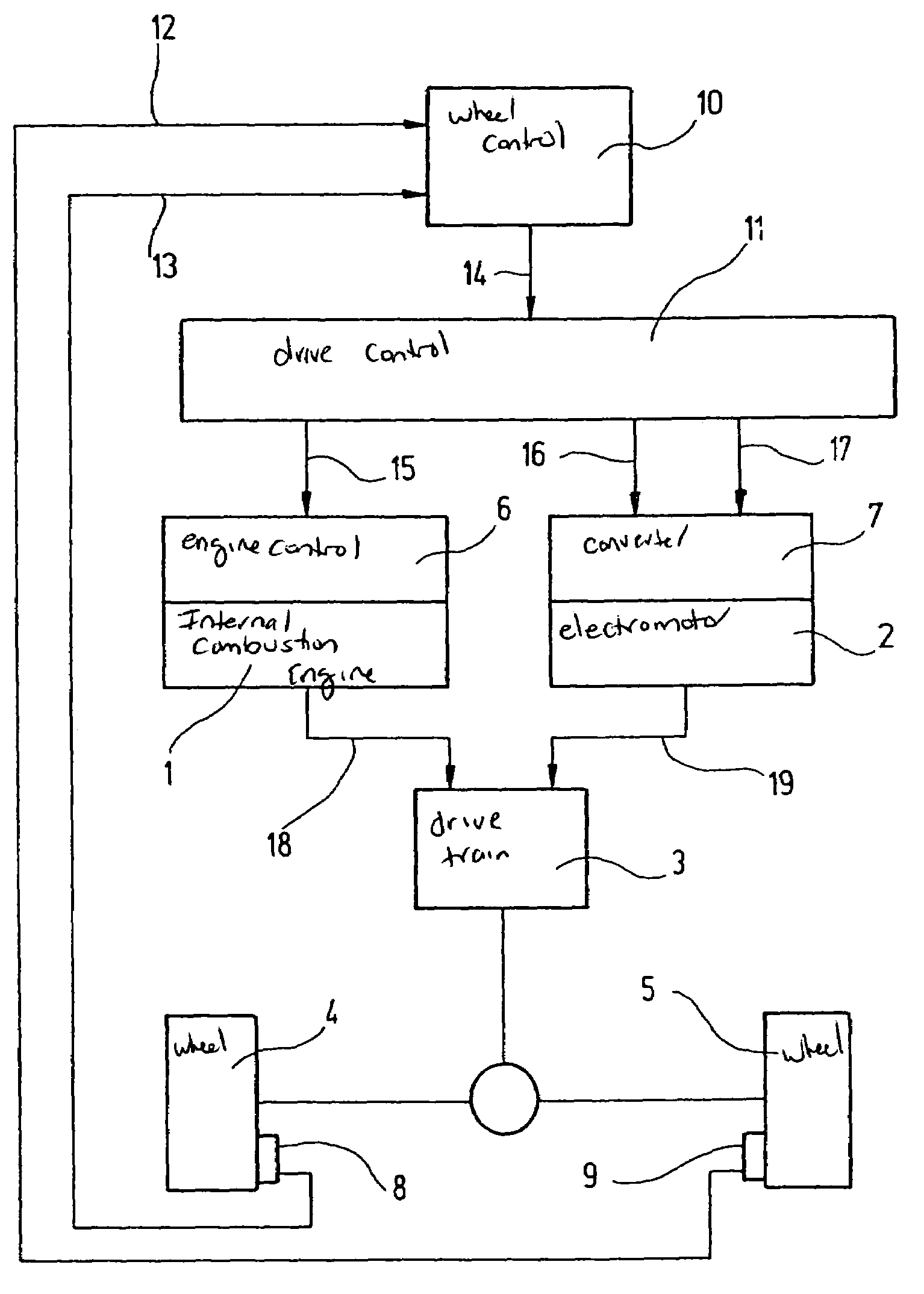
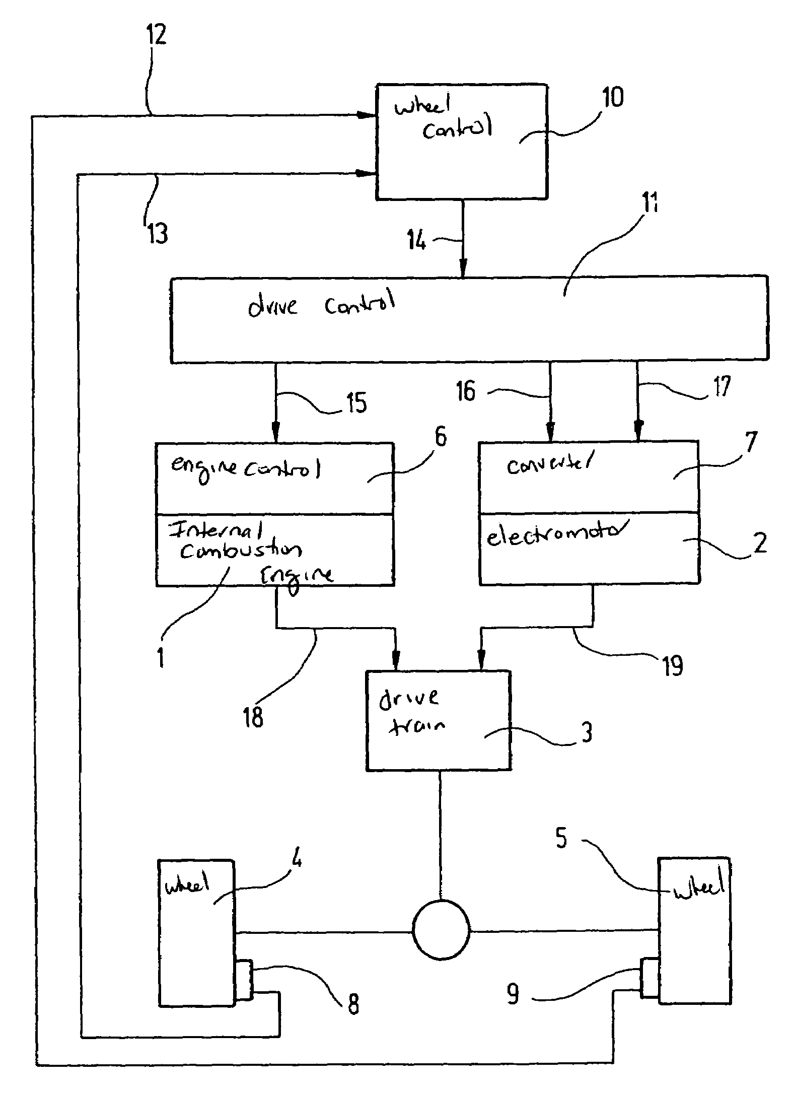
[0016]In the block diagram shown in the FIGURE, a hybrid vehicle having 2-wheel drive is assumed, in which an electromotor 2 is provided in addition to internal combustion engine 1. Via a transmission, internal combustion engine 1 as well as electromotor 2 are in operative connection with driven wheels 4, 5 of the hybrid vehicle. An engine control 6 is assigned to internal combustion engine 1, and a converter 7 to electromotor 2. Internal combustion engine 1 introduces a torque MVM (signal 18) and electromotor 2 introduces a torque MEM (signal 19) into the drive train.

[0017]In order to be able to increase the drive torque in these hybrid vehicles as quickly as possible when driven wheels 4, 5 exhibit brake slip in response to a load change, that is, in order to retain the lateral stability in a load change of the hybrid vehicle so that the hybrid vehicle retains its stability during driving even when brake slip occurs at driven wheels 4, 5 due to a load change, the drive torque is a...


PUM


Abstract

A method for regulating the drive torque following a load change in hybrid vehicles, in which the drive torque is influenced in a load change in that a brake slip at the driven wheel of the hybrid vehicle as a result of the load change is already counteracted in the beginning phase, in such a way that any effect on the lateral stability and thus the stability of the hybrid vehicle during driving is excluded. When brake slip occurs at the driven wheels because of a load change, the drive torque is applied via the electromotor(s) of the hybrid vehicle.

Description

FIELD OF THE INVENTION[0001]The present invention relates to a method for regulating the drive torque following a load change in hybrid vehicles, in which the drive torque is influenced in a load change in that a brake slip occurring at the driven wheel of the hybrid vehicle in response to the load change is already counteracted in the beginning phase, in such a way that an effect on the cornering stability and thus on the stability of the hybrid vehicle during driving is obviated. Furthermore, the present invention relates to a device for implementing the method of regulating the drive torque following a load change.BACKGROUND INFORMATION[0002]In motor vehicles it may happen that, because of the engine-drag torque, the driven wheels exhibit brake slip in response to a load change. This reduces the cornering stability of the motor vehicle and the motor vehicle becomes unstable. For this reason, it is necessary to reduce the brake slip as quickly as possible. It is conventional to us...

Claims


Application Information

Patent Timeline
Patent Type & Authority Patents(United States)
IPC IPC(8): B60K28/16G06F17/00G06F7/14B60L3/10F02D29/02B60L15/00B60L50/16B60W20/00G05D1/00
CPCB60W10/06B60W10/08B60W30/18109B60L2240/423B60T2201/09Y02T10/642B60W2520/26B60W2710/083Y02T10/6286B60W20/00Y02T10/64Y02T10/62
Inventor MAIER-LANDGREBE, ROLF
Owner ROBERT BOSCH GMBH
Learn More