
Method for preparing catalyst supports and supported catalysts from single walled carbon nanotubes

a technology of carbon nanotubes and supports, which is applied in the direction of catalyst activation/preparation, physical/chemical process catalysts, metal/metal-oxide/metal-hydroxide catalysts, etc., can solve the exact chemical nature of the active catalyst component within the reaction zone that is difficult to determine, and the pores are difficult to access, so as to achieve a high-accessible surface area

Inactive Publication Date: 2008-07-08
HYPERION CATALYSIS INT
View PDF29 Cites 83 Cited by
  • Summary
  • Abstract
  • Description
  • Claims
  • Application Information

AI Technical Summary

Benefits of technology

The resulting carbon structures exhibit improved mechanical strength, increased accessibility, and purity, making them suitable for applications requiring fluid passage and high mechanical integrity, such as catalyst supports, filters, and electrodes, while maintaining high surface area and resistance to attrition.

Problems solved by technology

Because heterogeneous reactions are normally carried out at elevated temperatures (and sometimes at elevated pressures as well) and in a reactive atmosphere, the exact chemical nature of the active catalyst component within the reaction zone can be difficult to determine.
These pores can be difficult to access because of diffusion limitations.
Moreover, they are easily plugged and thereby deactivated.
The cost of replacing attritted catalyst, the cost of separating it from the reaction mixture and the risk of contaminating the product are all burdens upon the process.
In other processes, e.g. where the solid supported catalyst is filtered from the process stream and recycled to the reaction zone, the fines may plug the filters and disrupt the process.
In the case of a catalyst support, this is even more important since the support is a potential source of contamination both to the catalyst it supports and to the chemical process.
Further, some catalysts are particularly sensitive to contamination that can either promote unwanted competing reactions, i.e., affect its selectivity, or render the catalyst ineffective, i.e., “poison” it.
Carbons made from natural resources may contain these materials as well as metals common to biological systems and may be undesirable for that reason.
While activated charcoals and other carbon-containing materials have been used as catalyst supports, none have heretofore had all of the requisite qualities of porosity and pore size distribution, resistance to attrition and purity for use in a variety of organic chemical reactions.
One of the characteristics of the prior aggregates of nanotubes, assemblages or mats made from nanotubes is low mechanical integrity and high compressibility.
Since the fibers are not very stiff these structures are also easily compressed or deformed.
As a result the size of the structures cannot be easily controlled or maintained during use.
The compressibility and / or lack of rigidity of previous structures of nanotubes creates serious limitations or drawbacks for such applications.
Differences in degree of graphitization, orientation and crystallinity of graphite planes, if they are present, the potential presence of heteroatoms and even the absolute difference in substrate diameter make experience with continuous fibers poor predictors of nanotube chemistry.
The previously discussed electric arc discharge and laser deposition methods cannot economically be scaled up for such commercial or industrial production.

Method used


Image

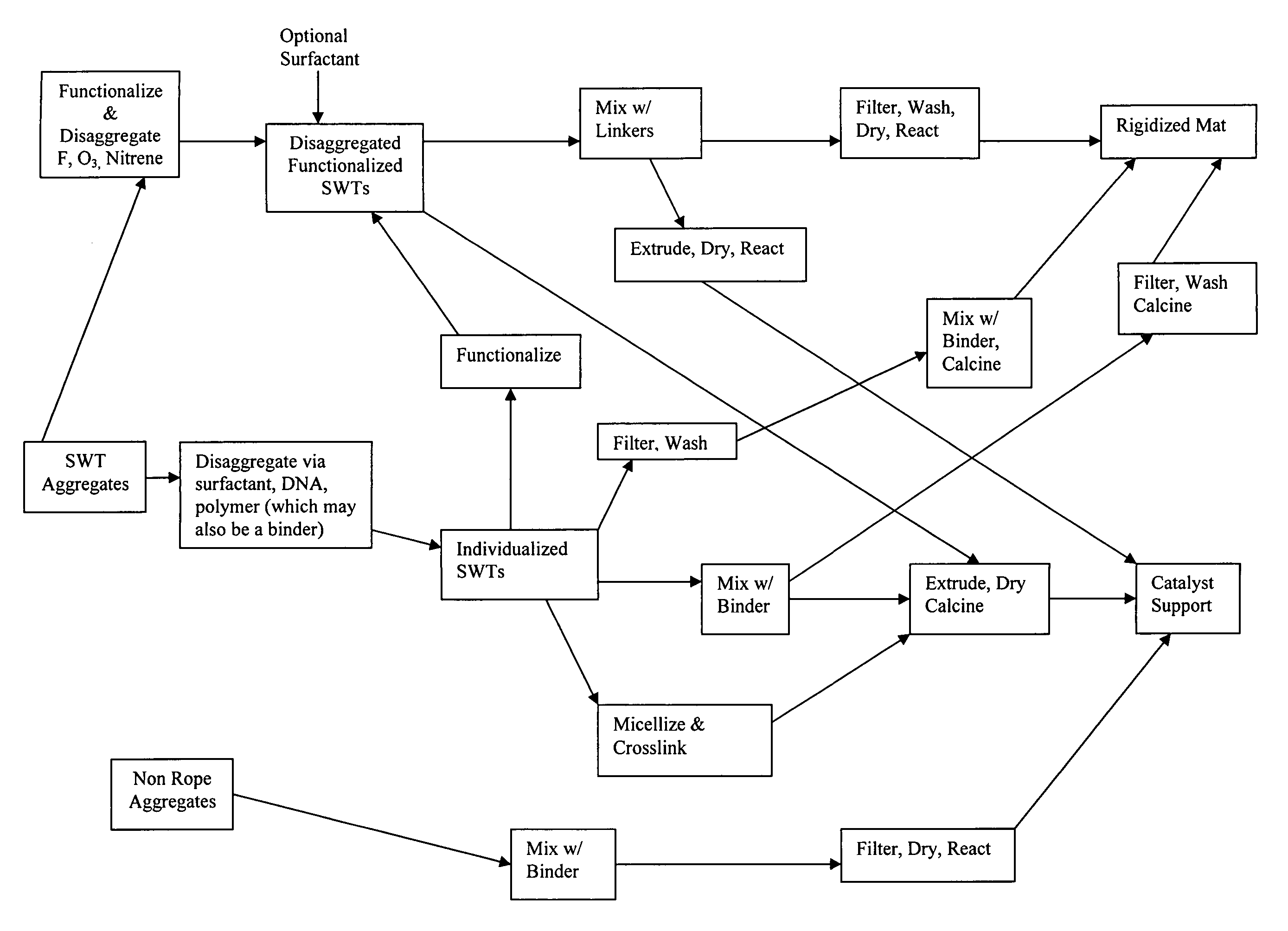
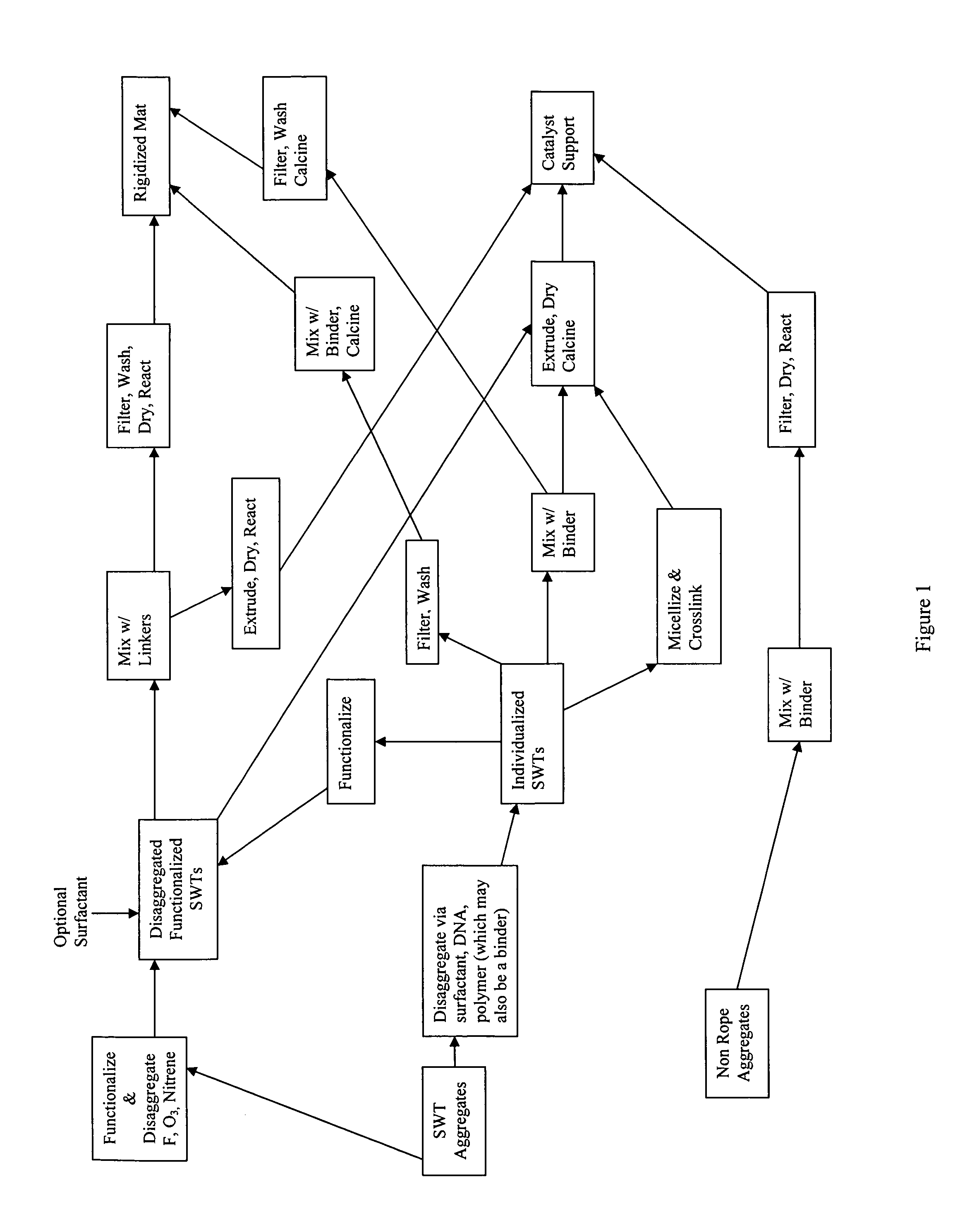
  • Method for preparing catalyst supports and supported catalysts from single walled carbon nanotubes
  • Method for preparing catalyst supports and supported catalysts from single walled carbon nanotubes
  • Method for preparing catalyst supports and supported catalysts from single walled carbon nanotubes

Examples


example 1

Dissaggregation of SWNTs with a Surfactant

[0129]Single-walled nanotubes made from a method described in U.S. Pat. No. 6,827,919 are first treated with 20% HCl to remove any residual metal catalysts responsible for making such material. The treated material is captured on a filter and washed with DI water until the filtrate is neutral pH. The washed nanotubes are then suspended in 1 wt. % aqueous solution of sodium dodecylsulfate (SDS) and subjected to high shear using a probe sonicator for four hours to generate mostly individualized single-walled nanotubes (Sample A).

example 2

Mixing Disaggregated SWNTs with Aqueous Binder

[0130]Disaggregated SWNTs (Sample A of Example 1) are concentrated by centrifugation to a level of 2 wt %. Poly(acrylic acid-co-maleic acid), 50% solution in water is added to obtain a 1:1 ratio of polymeric binder to nanotubes. The resulting paste like material is blended in a Retsch mortar mill to a uniform consistency (Sample B). The uniform nanotube paste, Sample B, is extruded through a die with a circular aperture forming a strand. The stand is cut to shorter lengths and dried at 200° C. in air overnight after which it is calcined at 600° C. in an argon atmosphere for 6 hours to produce rigid, porous catalyst support particles.

example 3

Dissaggregation of SWNTs with a Polymeric Binder

[0131]Single-walled nanotubes made from a method described in U.S. Pat. No. 6,827,919 are first treated with 20% HCl to remove any residual metal catalysts responsible for making such material. The treated material is captured on a filter and washed with DI water until the filtrate is neutral pH. The washed nanotubes are then suspended Di water to a level of 0.05 wt % in 1 wt. % aqueous gum Arabic and then subjected to high shear using a probe sonicator for four hours to generate mostly individualized single-walled nanotubes (Sample C).


PUM

PropertyMeasurementUnit
surface areaaaaaaaaaaa
surface areasaaaaaaaaaa
pore diametersaaaaaaaaaa

Abstract

A new method for preparing a supported catalyst is herein provided. A carbon nanotube structure such as a rigid porous structure is formed from single walled carbon nanotubes. A metal catalyst is then loaded or deposited onto the carbon nanotube structure. The loaded carbon nanotube is preferably ground to powder form.

Description

CROSS REFERENCE INFORMATION[0001]This application claims benefit to and priority of U.S. Provisional Application No. 60 / 628,678, filed Nov. 17, 2004, which is hereby incorporated by reference in its entirety.FIELD OF THE INVENTION[0002]The invention relates generally to method for preparing rigid porous carbon structures from single walled carbon nanotubes. More specifically, the invention relates to rigid three dimensional structures comprising carbon nanotubes and having high surface area and porosity, low bulk density, low amount of micropores and high crush strength and to methods of preparing and using such structures. The invention also relates to using such rigid porous structures for a variety of purposes including catalyst supports, electrodes, filters, insulators, adsorbents and chromatographic media and to composite structures comprising the rigid porous structures and a second material contained within the carbon structures.BACKGROUND OF THE INVENTIONCatlyst Supports and...

Claims


Application Information

Patent Timeline
Patent Type & Authority Patents(United States)
IPC IPC(8): B01J21/18B01J23/40B01J23/74B32B5/16B32B5/24B32B9/00D01F9/12D02G3/00D21H11/00B01J35/00
CPCB01J21/185B01J23/40B01J37/04B82Y30/00B01J37/0009B01J35/1023B01J35/1061B01J35/109Y10T428/2938Y10T428/25Y10T428/30Y10T428/2918Y02P20/582Y10T428/249967Y10T428/249962B01J35/617B01J35/69B01J35/647
Inventor MA, JUNMOY, DAVIDTENNENT, HOWARDHOCH, ROBERTFISCHER, ALAN
Owner HYPERION CATALYSIS INT
Learn More