
Opposed current flow magnetic pulse forming and joining system

a current flow and magnetic pulse technology, applied in the field of magnetic pulse technology, can solve the problems of limited use of magnetic pulse technology in the field of magnetic pulse forming and joining, coils that have not allowed the application of magnetic pulse technology to workpieces, and the use of split concentrators with closed coil devices does not provide the flexibility needed in many situations, so as to reduce the inductance of conductors

Active Publication Date: 2008-07-08
EDISON WELDING INSTITUTE INC
View PDF12 Cites 8 Cited by
  • Summary
  • Abstract
  • Description
  • Claims
  • Application Information

AI Technical Summary

Benefits of technology

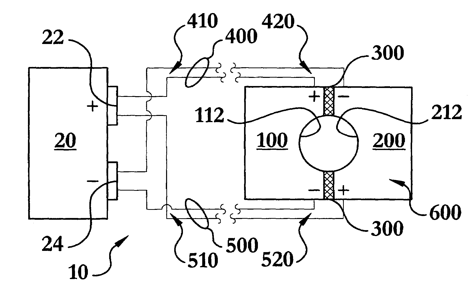
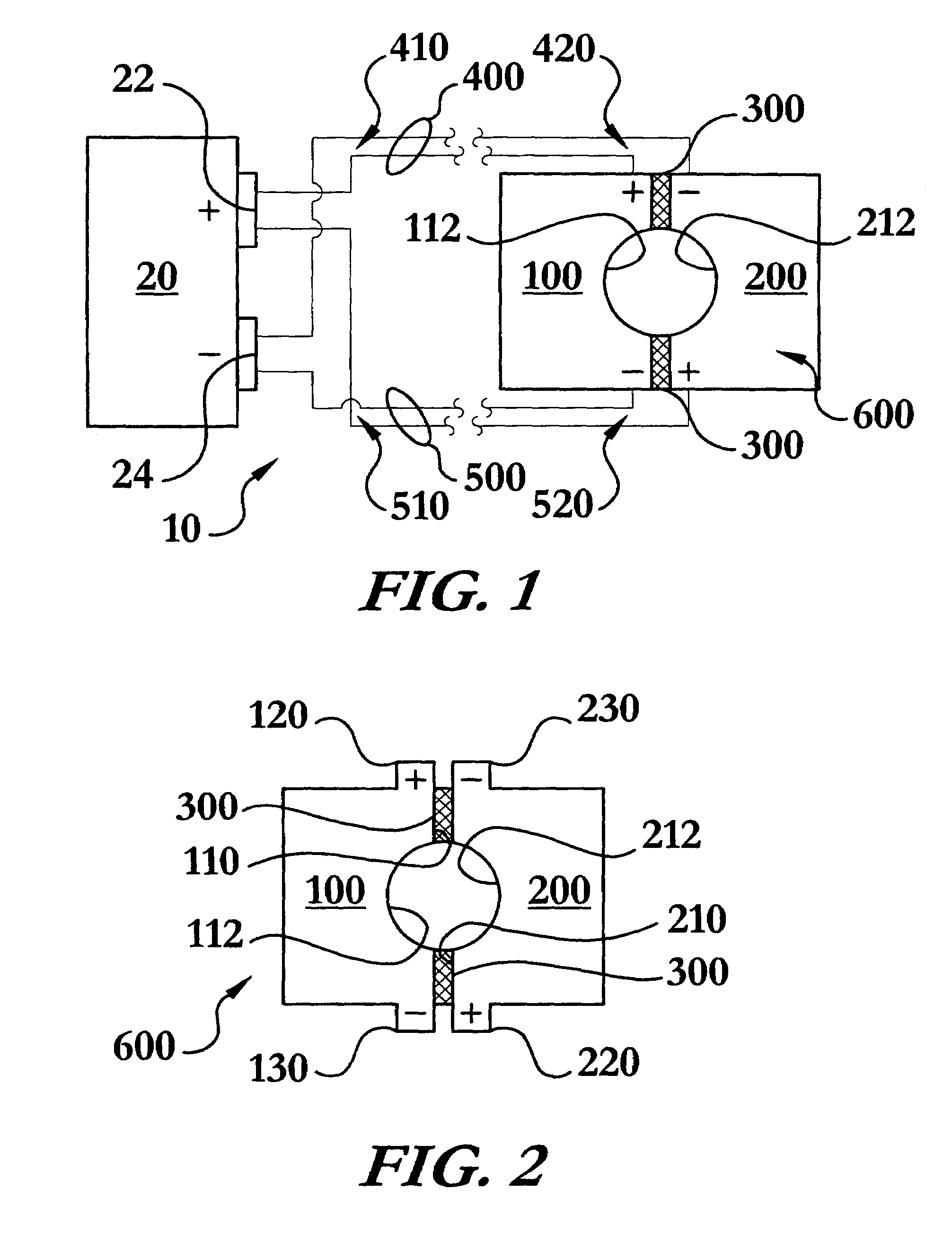
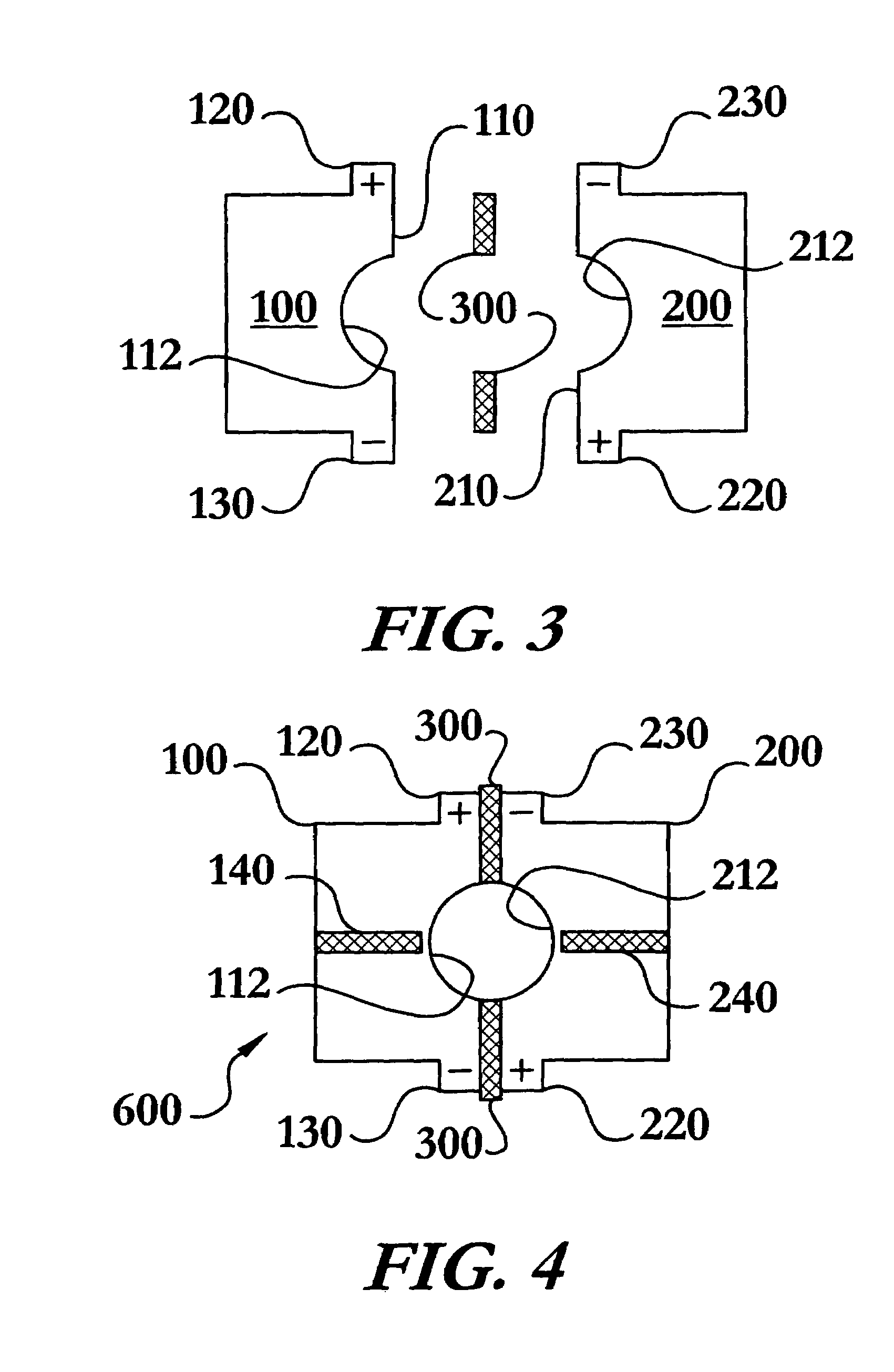
[0009]The present invention includes several systems and methods for performing magnetic pulse forming and joining with improved quality, reliability, and dramatically less losses due to inductance in the conductors. In one of the many preferable configurations, the opposed current flow magnetic pulse forming and joining system of the present invention is in electrical communication with a magnetic pulse power supply having a positive connection and a negative connection. The system may be used in forming an individual workpiece or joining multiple workpieces.
[0011]The system is configured to achieve desirable current flow throughout the system by minimizing the inductance in the conductors. The desired current flow is through the first section in a direction opposite the current flowing through the second section, while the current flows in opposite directions in each conductor of each pair of conductors. This current flow permits the first and second sections to function as if a single magnetic pulse coil, and the opposed current in the individual conductor pairs greatly reduces inductance in the conductors, affording several benefits not previously found in magnetic pulse systems.

Problems solved by technology

The widespread use of magnetic pulse forming and joining has been generally limited to use with tubular workpieces of relatively simple geometries.
Such closed coils have not allowed the application of magnetic pulse technologies to workpieces having anything other than simple shapes.
Still, use of a split concentrator with a closed coil device does not provide the flexibility needed in many situations; after all the formed or welded workpiece must still be able to slide out of the coil.
Such configurations have been plagued by sparking along the interface between the two sections which leads to premature wear and failure of the coil.
Yet another problem plaguing magnetic pulse technology systems has been the lack of control of the current as it passes through the sections.
Prior art systems have failed to recognize the importance that the electrical characteristics of the entire system have on the current flow within the sections.
The power transmission systems responsible to transmitting hundreds of thousands of amperes at an electrical potential of thousands of volts are generally the source of several problems.
Large power transmission circuits operating at the frequencies used in magnetic pulse forming and joining, generally tens of kHz, produce large inductance loads which negatively impact the operation.
First, high inductance in a magnetic pulse system has the effect of reducing the magnitude of the current, which consequently reduces the magnitude of the electromagnetic pulse force.
Secondly, high inductance in a magnetic pulse system has the effect of reducing the current frequency in the system, which consequently increases the rise time of the magnetic pulse force, which is particularly important in magnetic pulse welding.
Prior magnetic pulse technology systems have not been designed with reduction of inductance of the conductors, and all the associated benefits, in mind.

Method used


Image

  • Opposed current flow magnetic pulse forming and joining system
  • Opposed current flow magnetic pulse forming and joining system
  • Opposed current flow magnetic pulse forming and joining system

Examples


Embodiment Construction

[0030]The opposed current flow magnetic pulse forming and joining system 10 of the present invention enables a significant advance in the state of the art. The preferred embodiments of the method and system accomplish this by new and novel methods that are configured in unique and novel ways and which demonstrate previously unavailable but preferred and desirable capabilities. The description set forth below in connection with the drawings is intended merely as a description of the presently preferred embodiments of the invention, and is not intended to represent the only form in which the present invention may be constructed or utilized. The description sets forth the designs, functions, means, and methods of implementing the invention in connection with the illustrated embodiments. It is to be understood, however, that the same or equivalent functions and features may be accomplished by different embodiments that are also intended to be encompassed within the spirit and scope of t...


PUM

PropertyMeasurementUnit
lengthaaaaaaaaaa
inductanceaaaaaaaaaa
lengthaaaaaaaaaa

Abstract

An opposed current flow magnetic pulse forming and joining system in electrical communication with a magnetic pulse power supply having a positive connection and a negative connection. The system may be used in forming individual workpieces or joining multiple workpieces, including joining by magnetic pulse welding. The system includes a first section, a second section, an insulator, and a first and a second pair of conductors. The first and second sections cooperate to enclose the workpiece(s) and function to create an electromagnetic force similar to that produced by a single closed coil. The system is configured to achieve desirable current flow by minimizing inductance, inductive reactance, and impedance in the conductors. The pairs of conductors may incorporate closely spaced individual conductors, braided conductors, and coaxial conductors. The current flow in the individual conductors of each pair of conductors is opposed, as is the current flow through the sections.

Description

STATEMENT REGARDING FEDERALLY SPONSORED RESEARCH OR DEVELOPMENT[0001]This invention was not made as part of a federally sponsored research or development project.TECHNICAL FIELD[0002]The present invention relates to the field of magnetic pulse technologies, namely magnetic pulse forming and magnetic pulse joining, including welding, and related systems and methods. The present invention is an opposed current flow magnetic pulse forming and joining system.BACKGROUND OF THE INVENTION[0003]The use of magnetic pulse technologies in forming and joining components has been known for years. The widespread use of magnetic pulse forming and joining has been generally limited to use with tubular workpieces of relatively simple geometries. Traditionally, magnetic pulse forming and joining has been accomplished through the use of a closed coil configured such that the parts to be formed or joined can be slid into and out of the coil. Such closed coils have not allowed the application of magneti...

Claims


Application Information

Patent Timeline
Patent Type & Authority Patents(United States)
IPC IPC(8): B23P19/00B21D26/02
CPCB21D26/14B21J7/30B23K20/06Y10T29/49803Y10T29/49805Y10T29/53417B23K2201/06B23K2101/06
Inventor SHAO, HAIPINGZHANG, PEIHUI
Owner EDISON WELDING INSTITUTE INC
Learn More