
Distributed train control

a technology of distributed control and trains, applied in the field of trains, can solve the problems of not being considered “vital”, high reliability, and communication protocols not being conformed,

Active Publication Date: 2008-07-01
GE GLOBAL SOURCING LLC
View PDF8 Cites 98 Cited by
  • Summary
  • Abstract
  • Description
  • Claims
  • Application Information

AI Technical Summary

Benefits of technology

[0010]According to another aspect of the invention, a control system is provided for a train including a lead power unit, at least one remote power unit, and at least one car having a braking system. The control system includes: (a) a targeted braking system operably coupled to the braking system, the targeted braking system programmed to: (i) identify a braking target located at a position ahead of the train; (ii) transmit braking target data over a communications channel; and (iii) activate the braking system at a braking point located prior to the braking target, the braking point being determined in accordance with a predetermined braking curve. The system also includes (b) a remote brake control system operably connected to the braking system, the remote brake control system programmed to: (i) receive the braking target data; (ii) transmit a confirmation to the targeted braking system over the communications channel that it is armed to the braking target; and (iii) activate the braking system at the braking point.
[0011]According to yet another aspect of the invention, a method is prov

Problems solved by technology

Known DP systems such as the one described above are highly reliable, but are not generally considered “vital”, i.e., their communications protocols do not conform to any specific standards for safety-critical train control operations that must be implemented in a fail-safe manner.

Method used


Image

  • Distributed train control
  • Distributed train control
  • Distributed train control

Examples


Embodiment Construction

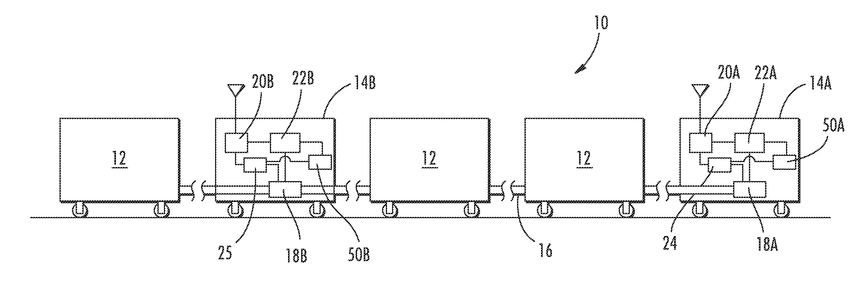
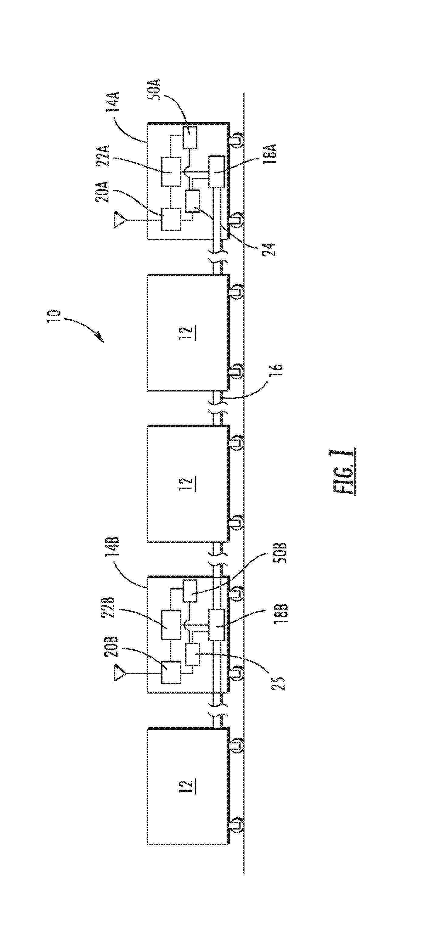
[0018]Referring to the drawings wherein identical reference numerals denote the same elements throughout the various views, FIG. 1 depicts a train 10 incorporating a distributed control system constructed according to an aspect of the present invention. The train 10 includes a plurality of coupled cars 12, and two or more locomotives or other units which provide tractive force, referred to herein generally as “power units”14. The individual cars 12 are coupled together by a brake pipe 16 which conveys air pressure changes specified by individual air brake controllers 18 in the power units 14. As used herein, the term “air brake controller” refers generally to one or more components which cooperate to selectively hold or release pressure from the brake pipe 16 and may include mechanical valves, electrical, or electronic controls associated with those valves, or combinations thereof. Each of the cars 12 is provided with a known type of air brake system which functions to apply air bra...


PUM


Abstract

A method of distributed control of train throttle and braking includes transmitting an instruction to a remote power unit to apply at least one acceleration to the train at a future time; receiving the instruction; transmitting a confirmation that the remote power unit is armed to execute the instruction to a lead power unit; and computing a profile describing at least one acceleration to be applied to the train as it travels over a predetermined route. The computation is determined at least in part on whether or not the confirmation has been received by the lead power unit. The instructions may be contained in a profile which optimizes fuel consumption, emissions, and / or trip time. The accelerations may be carried out by direct control or by prompting an operator. In another aspect, the confirmed instructions may be used to ensure braking in accordance with a predetermined braking curve.

Description

BACKGROUND OF THE INVENTION[0001]This invention relates generally to trains and other rail vehicles and more particularly to systems and methods for distributed control of trains.[0002]Train cars are commonly provided with a type of air brake system which functions to apply brakes on the car upon a pressure drop in a “brake pipe” that interconnects the cars and to release the air brakes upon a pressure rise in the brake pipe. The brake pipe is pressurized by a compressor in the locomotive. When braking is desired, a brake valve in the locomotive bleeds air from the brake pipe through an orifice.[0003]Such air brake systems may be controlled by a system referred to as communication based train control (“CBTC”) or positive train control (“PTC”). In a PTC system, speed limits, temporary slow orders, movement authorities and other conditions are conveyed to a train cab using electrical signals on the rails, transponders, or wireless transmission so that aspect information can be directl...

Claims


Application Information

Patent Timeline
IPC IPC(8): G06F19/00
CPCB61C17/12B61L15/0027B61L3/008B61L15/0062
Inventor SECK, DARYL WILLIAMNOFFSINGER, JOSEPH FORRESTFOY, ROBERT JAMES
Owner GE GLOBAL SOURCING LLC
Learn More