
Interaction between objects and a virtual environment display

a virtual environment and display technology, applied in the field of interaction between objects and virtual environment displays, can solve the problems of inability to detect the shape, the inability of sensors to detect more than a point of contact, and the plurality of different types, etc., and achieve the effect of facilitating interaction

Inactive Publication Date: 2008-07-01
MICROSOFT TECH LICENSING LLC
View PDF23 Cites 202 Cited by
  • Summary
  • Abstract
  • Description
  • Claims
  • Application Information

AI Technical Summary

Benefits of technology

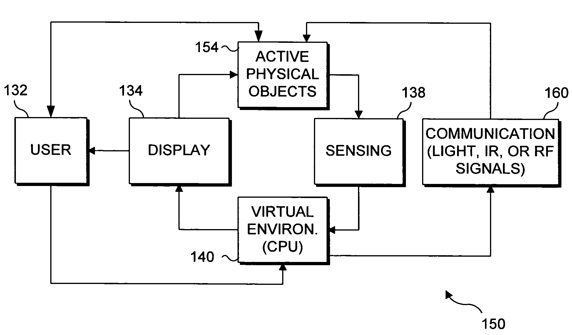
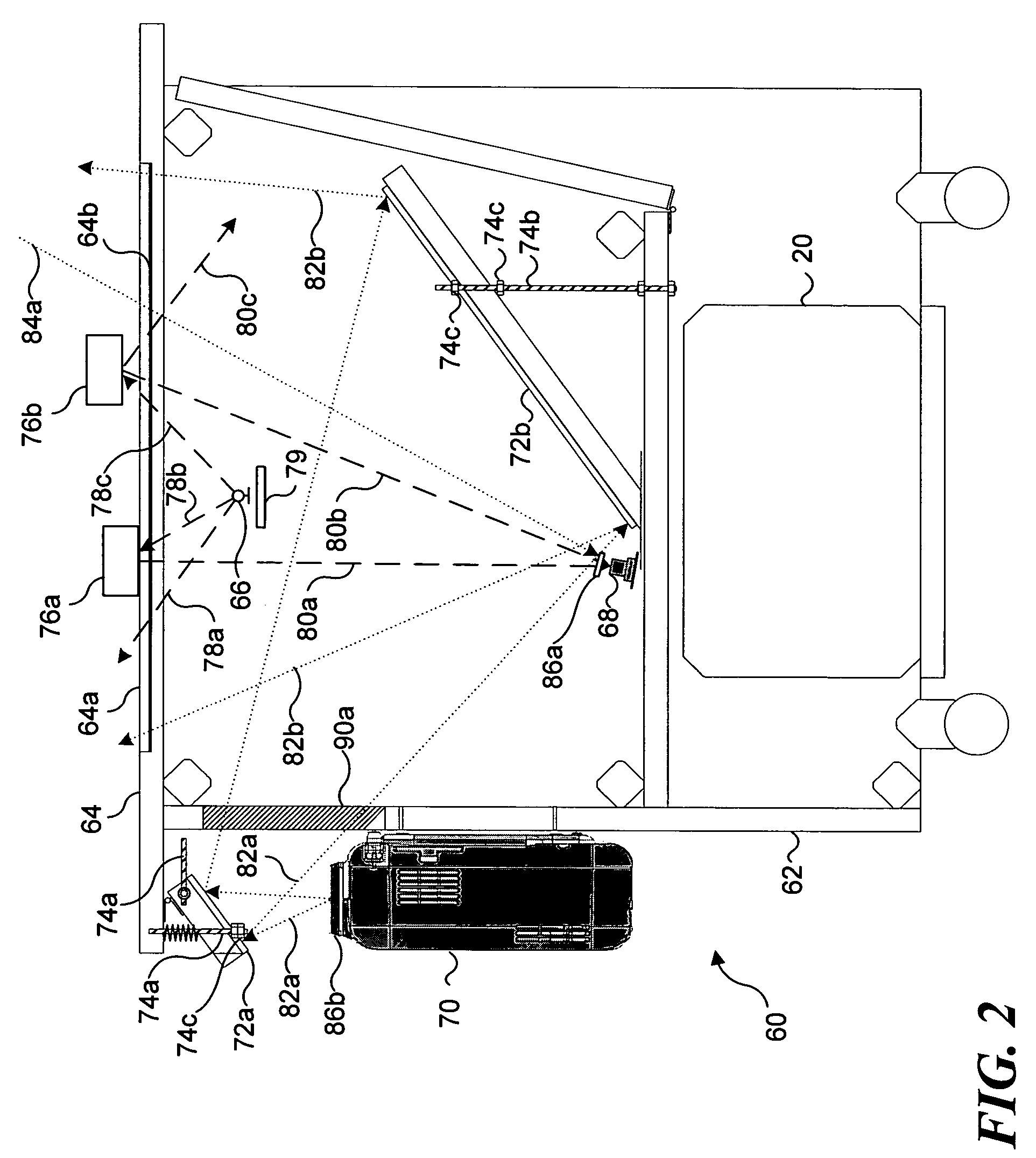
[0011]The present invention enables a blurring of the distinction between the real world of physical objects and a virtual environment in which virtual objects and graphic images are displayed on a display screen. To achieve this result, an interactive display has been developed that includes a display surface formed as the central part of a table top. A virtual environment is projected from below and viewed on the display surface. Any physical object that is disposed on the display surface can be optically detected by an IR camera that is disposed below the display surface and which is responsive to IR light that is reflected from the physical object. Once the physical object has been detected at a specific position using the camera, a software program controlling the virtual environment or graphic images being displayed then facilitates an interaction between the physical object and the virtual environment just as if the physical object were included within the virtual environment. Depending upon the type of physical object that is positioned atop the display surface, the interaction can be in two different modes. Specifically, in a first mode, the virtual environment that is displayed responds to the presence of the physical object on the display surface. In the second mode, the physical object responds to the virtual environment that is displayed, particularly, to changes in the virtual environment or graphic images that are displayed on the displayed surface.
[0013]The response to the physical object can also be implemented by the interaction of a virtual object in the virtual environment with the physical object. Thus, for example, the virtual object can be prevented from moving through a region in the virtual environment where the physical object is located on the display surface. If the physical object represents a wall in the virtual environment, a virtual object corresponding to a car controlled by a software program displaying the virtual environment would be caused to steer away from and avoid colliding with the wall at the location of the physical object on the display screen. This method can also detect at least one of a size and a shape of the physical object at a specific location on the display surface to enable the predefined response to the physical object within the virtual environment.
[0017]Since a location of the physical object is determined in this method, a virtual entity can be displayed at a position on the display surface selected to avoid a visual interference between the virtual object and the physical object. The virtual entity comprises either a virtual object or information. Preferably, a plurality of prioritized or ordered positions are determined at which the virtual entity can be selectively displayed to avoid the interference with the physical object. A position that avoids the interference with the physical entity and having a highest priority is selected for display of the virtual entity. Also, the method preferably determines a location of a specific user who will be visually perceiving the virtual entity, so that the virtual entity is oriented and displayed at a position selected to enable the specific user to easily visually perceive the virtual entity. This position will be selected to avoid visual interference between the physical object and the virtual entity. If the virtual entity cannot be displayed without interference with the physical object at a highest priority location, a size of the virtual entity can be reduced to avoid the interference with the physical object.

Problems solved by technology

However, in most such touch-sensitive displays, the response is only to the touch of the finger or stylus at a point.
However, the capacitive, electromagnetic, optical, or other types of sensors used in conventional touch-sensitive displays typically cannot simultaneously detect the location of more than one finger or object touching the display screen at a time, and thus, would be unable to detect the location or each different type of a plurality of different types of physical objects placed thereon.
These prior art touch-sensing systems are generally incapable of detecting more than a point of contact and are unable to detect the shape of an object proximate to or touching the display surface.
Even capacitive or resistive, or acoustic surface wave sensing display surfaces that can detect multiple points of contact are unable to image objects on a display surface to any reasonable degree of resolution.
Prior art systems of these types cannot detect patterns on an object or detailed shapes that might be used to identify each object among a plurality of different objects that are placed on a display surface.
This multiple camera mounting configuration is clearly not a compact system that most people would want to use in a residential setting.
Furthermore, the view of one object by one of the cameras may be blocked by an intervening object.
However, there is no discussion of active objects being placed on the surface of the display panel to carry out some active function involving an interaction with a virtual environment displayed on the screen.

Method used


Image

  • Interaction between objects and a virtual environment display
  • Interaction between objects and a virtual environment display
  • Interaction between objects and a virtual environment display

Examples


Embodiment Construction

Exemplary System for Implementing Present Invention

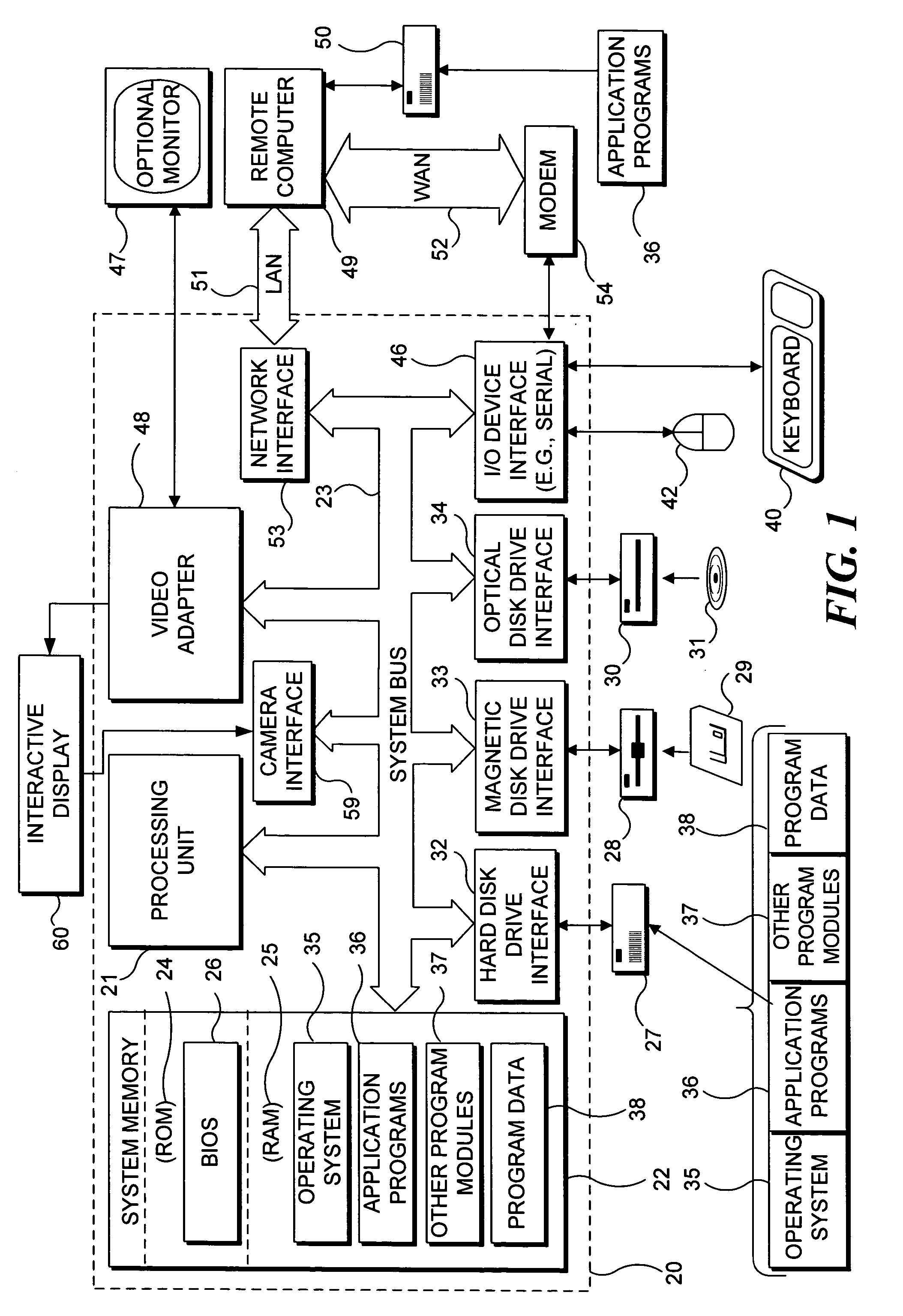
[0033]With reference to FIG. 1, an exemplary system suitable for implementing various portions of the present invention. The system includes a general purpose computing device in the form of a conventional PC 20, provided with a processing unit 21, a system memory 22, and a system bus 23. The system bus couples various system components including the system memory to processing unit 21 and may be any of several types of bus structures, including a memory bus or memory controller, a peripheral bus, and a local bus using any of a variety of bus architectures. The system memory includes read only memory (ROM) 24 and random access memory (RAM) 25. A basic input / output system 26 (BIOS), containing the basic routines that help to transfer information between elements within the PC 20, such as during start up, is stored in ROM 24. The PC 20 further includes a hard disk drive 27 for reading from and writing to a hard disk (not shown), a mag...


PUM


Abstract

An interactive table has a display surface on which a physical object is disposed. A camera within the interactive table responds to infrared (IR) light reflected from the physical object enabling a location of the physical object on the display surface to be determined, so that the physical object appear part of a virtual environment displayed thereon. The physical object can be passive or active. An active object performs an active function, e.g., it can be self-propelled to move about on the display surface, or emit light or sound, or vibrate. The active object can be controlled by a user or the processor. The interactive table can project an image through a physical object on the display surface so the image appears part of the object. A virtual entity is preferably displayed at a position (and a size) to avoid visually interference with any physical object on the display surface.

Description

FIELD OF THE INVENTION[0001]This invention generally pertains to a method and apparatus wherein an interaction occurs between a virtual environment displayed on a surface and objects placed on the display surface, and more specifically, pertains to facilitating an interaction between graphic images displayed on a display surface and passive and / or active objects that are placed on or positioned near the display surface.BACKGROUND OF THE INVENTION[0002]Virtual environments are typically employed in electronic games that are played on game consoles, personal computers, and other types of computing devices, as well as in other types of applications. A user usually interacts with objects in a virtual environment by manipulating a mouse, joystick, wheel, game pad, track ball, or other user input device that causes the virtual object to move in a specific manner or carry out some other action or function as defined by the software program that produces the virtual environment. The effects...

Claims


Application Information

Patent Timeline
Patent Type & Authority Patents(United States)
IPC IPC(8): G06F3/042G06F3/01A63F9/24G06F1/16G06F3/00G06F3/03G06F3/041G06F3/0484G06F3/0487G06F19/00
CPCA63F13/00G06F3/016A63F3/00643G06F3/0425G06F3/011A63F2300/1075A63F2300/1087A63F2300/69A63F9/183G06F3/04815A63F13/213A63F13/65
Inventor BATHICHE, STEVENKURLANDER, DAVID JOSHUAWILSON, ANDREW D.CHEN, CHRISTINA SUMMERDEHLIN, JOEL P.
Owner MICROSOFT TECH LICENSING LLC
Learn More