
Droplet ejection head and image recording apparatus

a technology of droplet ejection and image recording, which is applied in the direction of printing, other printing apparatus, etc., can solve the problems of inability to eject droplets, incomplete ink ejection, and insufficient pressure to be applied to ink, so as to preserve the quality of outputted prints, increase ejection force, and maintain drive efficiency

Inactive Publication Date: 2008-06-17
FUJIFILM CORP
View PDF16 Cites 12 Cited by
  • Summary
  • Abstract
  • Description
  • Claims
  • Application Information

AI Technical Summary

Benefits of technology

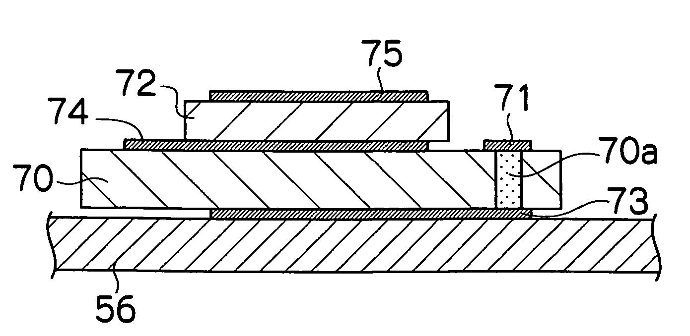
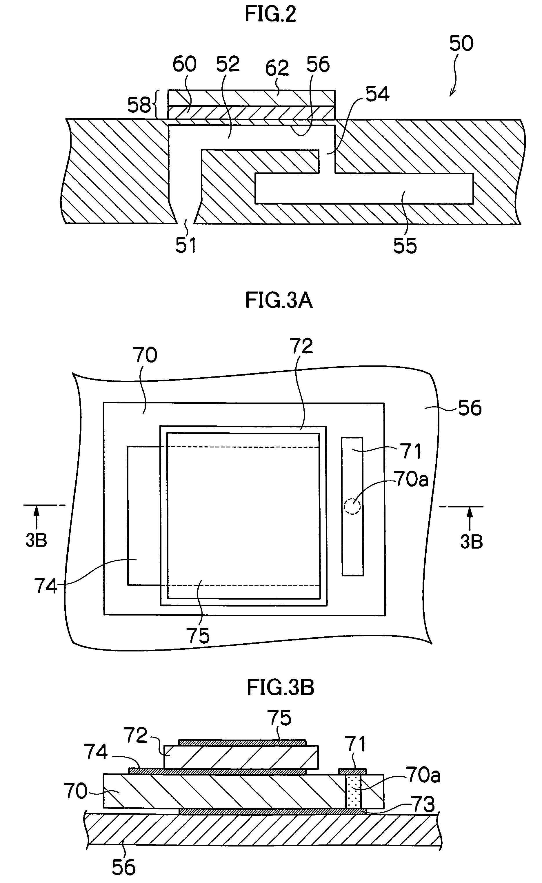
The present invention provides a droplet ejection head and image recording apparatus with an improved determination sensitivity and the ability to determine the oscillation state in the pressure chamber even while the heads are being driven. This is achieved by using an oscillation determining mechanism that includes a mechanoelectrical transducer and an electromechanical transducer arranged on the diaphragm in layers. The determination sensitivity is increased without decreasing the surface area occupied by the electromechanical transducer used for drive, and the mechanoelectrical transducer can be made of different materials for optimal driving and determination. The droplet ejection head and image recording apparatus can detect abnormalities during image recording and preserve the quality of the outputted prints.

Problems solved by technology

In such an inkjet head that uses a piezoelectric element, when air sometimes gets mixed in the ink held in the head, the variation of the pressure chamber capacity is absorbed by the air bubbles formed by this air, so that sufficient pressure cannot be applied to the ink any longer, and ink ejection thus becomes incomplete.
Moreover, ink droplets cannot be ejected when the nozzle is clogged with dirt or the like, or when the ink does not fill the pressure chamber.
However, this composition has problems in that a sufficient surface area is required for the mechanoelectrical transducer used for determination to be bonded onto the diaphragm, so that the surface area occupied by the electromechanical transducer used for drive must be decreased in proportion to the space to which the mechanoelectrical transducer used for determination is to be attached, which is inconvenient in terms of driving efficiency.
However, this composition has problems in that since some of the plurality of electromechanical transducers are used as mechanoelectrical transducers for determination by the switching circuit, the determination sensitivity is insufficient because the oscillation generated by some of the electromechanical transducers is determined on the adjacent diaphragm, and furthermore, the electromechanical transducer cannot be used for drive and ink cannot be ejected during the abnormality detecting process.

Method used


Image

  • Droplet ejection head and image recording apparatus
  • Droplet ejection head and image recording apparatus
  • Droplet ejection head and image recording apparatus

Examples


Embodiment Construction

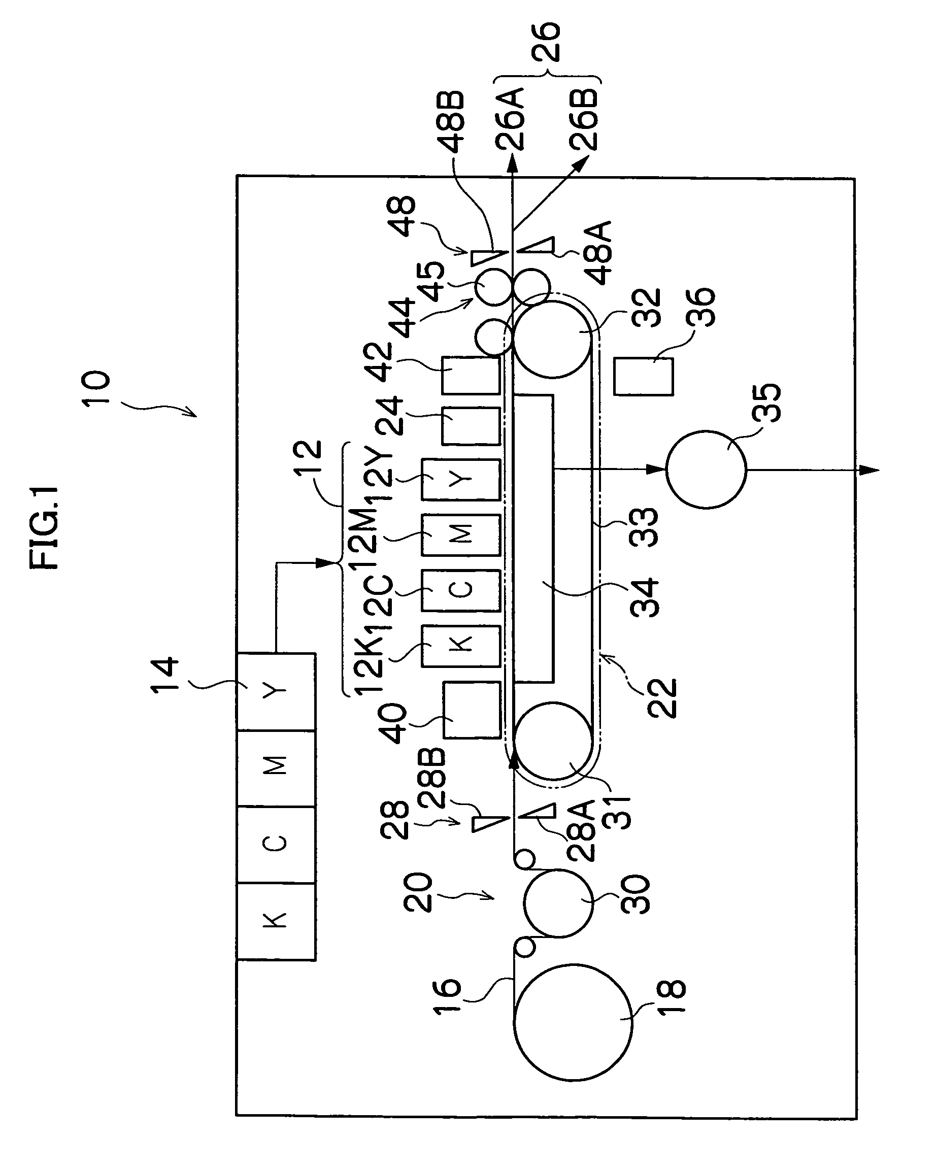
[0031]FIG. 1 is a general schematic drawing of an inkjet recording apparatus according to an embodiment of the present invention. As shown in FIG. 1, the inkjet recording apparatus 10 comprises: a printing unit 12 having a plurality of droplet ejection heads or print heads 12K, 12C, 12M, and 12Y for ink colors of black (K), cyan (C), magenta (M), and yellow (Y), respectively; an ink storing / loading unit 14 for storing inks to be supplied to the print heads 12K, 12C, 12M, and 12Y; a paper supply unit 18 for supplying recording paper 16; a decurling unit 20 for removing curl in the recording paper 16; a suction belt conveyance unit 22 disposed facing the nozzle face (ink-droplet ejection face) of the print unit 12, for conveying the recording paper 16 while keeping the recording paper 16 flat; a print determination unit 24 for reading the printed result produced by the printing unit 12; and a paper output unit 26 for outputting image-printed recording paper (printed matter) to the ext...


PUM


Abstract

The droplet ejection head comprises: a nozzle through which a droplet of liquid is ejected; a pressure chamber which is connected to the nozzle and filled with the liquid to be ejected through the nozzle; a diaphragm which defines a part of the pressure chamber; an electromechanical transducer which is deformed to drive the diaphragm to apply pressure to the liquid inside the pressure chamber so as to cause the droplet to be ejected through the nozzle; and a mechanoelectrical transducer which determines oscillation state in the pressure chamber, wherein the electromechanical transducer and the mechanoelectrical transducer are arranged on the diaphragm in layers.

Description

BACKGROUND OF THE INVENTION[0001]1. Field of the Invention[0002]The present invention relates to a droplet ejection head and an image recording apparatus, and more specifically to a droplet ejection head and an image recording apparatus having an improved configuration of an electromechanical transducer and a mechanoelectrical transducer for determining oscillation in a pressure chamber of the droplet ejection head using piezoelectric elements.[0003]2. Description of the Related Art[0004]One known example of an image recording apparatus is an inkjet recording apparatus having an inkjet head (print head) with an array of multiple nozzles (image recording elements), in which an image is formed on a recording medium by ejecting ink from the nozzles while moving the inkjet head and the recording medium relative to each other.[0005]There are various ink ejection systems for the inkjet head of such an inkjet recording apparatus. Known examples include a piezoelectric system in which a dia...

Claims


Application Information

Patent Timeline
Patent Type & Authority Patents(United States)
IPC IPC(8): B41J2/045B41J29/393B41J2/14
CPCB41J2/04581B41J2/04588B41J2/14233B41J2/14274B41J2002/14354
Inventor KAWAMURA, KAZUSHIGE
Owner FUJIFILM CORP
Learn More