
Method of manufacturing glass melt and method of manufacturing molded glass material

a manufacturing method and glass melt technology, applied in the direction of manufacturing tools, machines/engines, instruments, etc., can solve the problems of fluorine-containing glasses by the above method

Inactive Publication Date: 2008-06-10
HOYA CORP
View PDF19 Cites 79 Cited by
  • Summary
  • Abstract
  • Description
  • Claims
  • Application Information

AI Technical Summary

Benefits of technology

The patent describes a method of manufacturing glass melt containing fluorine by melting glass raw materials and refining the resulting glass melt. The refining is conducted in a refining vat equipped with a flow inlet and a flow outlet, with the level of the glass melt maintained in such a manner that the flow inlet and flow outlet remain beneath the surface of the glass melt and the glass melt does not contact external air. The method also includes monitoring the level of the glass melt in a surface monitoring vat and controlling the level of the glass melt in the surface monitoring vat to ensure that the connection opening in the surface monitoring vat remains constantly beneath the surface of the glass melt and the surface area of the glass melt within the surface monitoring vat is smaller than the maximum vertical cross-sectional area of the glass melt in the surface monitoring vat. The method can also involve discharging gas from the interior of the refining vat so that the level of the glass melt in the refining vat is identical to the level of the glass melt in the surface monitoring vat. The patent also describes a method of manufacturing molded glass material from the glass melt produced by the described method.

Problems solved by technology

However, in contrast to other glasses, the manufacturing of fluorine-containing glasses by the above method presents the following problems.
To efficiently remove bubbles from the glass, refining must normally be conducted at a temperature exceeding the melting temperature of the glass, and the above-stated loss of fluorine ions and related problems become marked in the refining vat.

Method used


Image

  • Method of manufacturing glass melt and method of manufacturing molded glass material
  • Method of manufacturing glass melt and method of manufacturing molded glass material

Examples


embodiments

Embodiment 1

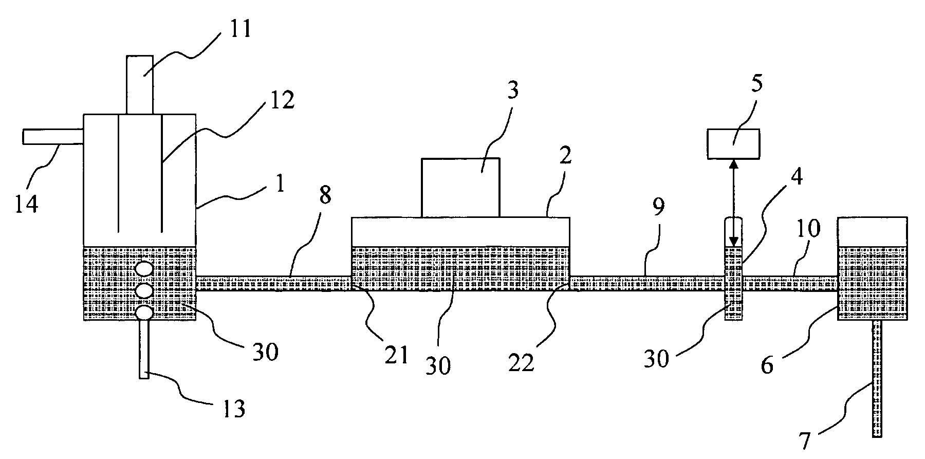
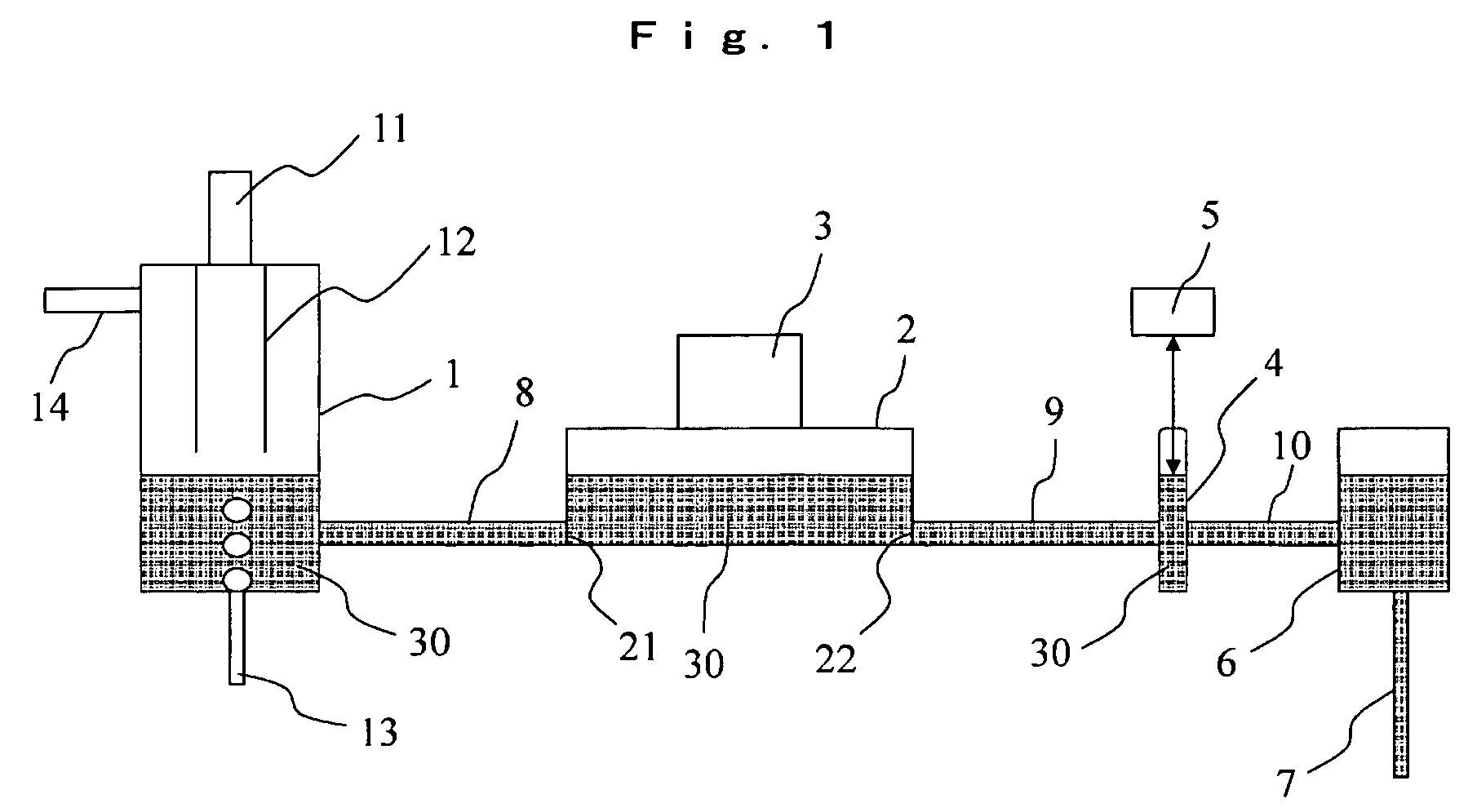
[0056]Embodiments will be described below with reference to the drawings.

[0057]FIG. 1 is a schematic view of a cross-section of a glass melting furnace employed in the present embodiment.

[0058]A glass raw material introduction opening 11 is provided in the upper portion of a melting vat 1 of platinum, through which a glass raw material obtained by blending multiple powdered compounds of various types is introduced to glass melt accumulating in the melting vat.

[0059]Fluorophosphate glass, a typical fluorine-containing glass, is an optical glass in which fluorine is used to raise the Abbé number (νd) and that exhibits a high degree of positive anomalous dispersivity. The raw materials are a fluorine compound MFx and a metaphosphate compound M′ (PO3)x′. Here, M and M′ each denote a metal element such as an alkali metal element or alkaline earth metal element, or one or multiple metal elements selected from among other metal elements. x and x′ denote the valence numbers of M...

embodiment 2

[0070]The molten fluorophosphate glass manufactured by the method of Embodiment 1 was made to flow out of a flow pipe at a constant flow rate into a casting mold and sheet glass comprised of the fluorophosphate glass was molded. The sheet glass was annealed and cut into prescribed shape to produce cut glass.

[0071]Next, the cut glass was reheated and press molded in a pressing mold to obtain a lens-shaped molded product. The molded product was ground and polished to manufacture lenses of low-dispersion optical glass. The lens obtained exhibited the desired optical characteristics.

embodiment 3

[0072]Molten copper-containing fluorophosphate glass manufactured by the method of Embodiment 1 was made to flow out of a flow pipe at a constant flow rate into a casting mold, and sheet glass comprised of fluorophosphate glass was molded. The sheet glass was annealed, sliced to prescribed thickness, and optically polished to manufacture the color-compensating filter of a solid-state image pickup element having a near infrared radiation-absorbing function. As a result, it was possible to obtain color-compensating filter glass for solid-state image pickup elements having an external transmittance of greater than or equal to 85 percent at a wavelength of 400 nm and an external transmittance of less than or equal to 22 percent at a wavelength of 1,200 nm as calculated based on conversion to a thickness of 0.45 mm. Due to high transmittance at a wavelength of 400 nm and low transmittance at a wavelength of 120 nm, a good color-compensation function was achieved.

[0073]When copper-contain...


PUM

PropertyMeasurementUnit
modulation frequencyaaaaaaaaaa

Abstract

A method of manufacturing glass melt and a method of manufacturing molded glass material by forming glass melt. In the method of manufacturing glass melt, the glass melt containing fluorine is prepared by melting glass raw materials and refining the resulting glass melt. The refining is conducted in a refining vat equipped with a flow inlet through which flows glass melt obtained by heating and melting the glass raw materials, and a flow outlet through which flows glass melt that has been refined, with the level of the glass melt being maintained in such a manner that the flow inlet and flow outlet remain beneath the surface of the glass melt and the glass melt does not contact external air. The method of manufacturing a molded glass material comprises the step of molding the glass melt produced by the above method.

Description

TECHNICAL FIELD[0001]The present invention relates to a method of manufacturing glass melt and a method of manufacturing molded glass material by forming glass melt.BACKGROUND ART[0002]There are known glass melting furnaces, employed in the manufacturing of high-quality glass by heating and melting glass raw materials, that are equipped with a melting vat that heats and melts glass raw materials, a refining vat in which foam is removed from glass that has been melted in the melting vat, and a homogenization vat in which the refined glass is stirred, with the various vats being connected by pipes. For example, Japanese Unexamined Patent Publication (KOKAI) No. 2000-128548 (Reference 1) discloses such a glass melting furnace.[0003]To adequately defoam the glass, the refining vat in the glass melting furnace of Reference 1 is of prescribed shape and gas discharge holes for removing gas generated by the glass melt are provided in the upper portion of the refining vat.[0004]Such methods ...

Claims


Application Information

Patent Timeline
Patent Type & Authority Patents(United States)
IPC IPC(8): C03B5/00C03B3/00C03B5/193C03B5/225C03B5/24C03B11/00G01F23/292
CPCC03B5/193C03B5/225C03B5/245G01F23/292
Inventor ICHINOSE, JUNOGINO, KAZUOKATO, HIDETSUGU
Owner HOYA CORP
Learn More