
Storage apparatus, and control method and program

a technology for storage apparatus and control method, applied in the field of storage apparatus, can solve problems such as retry, write fault, error detection, etc., and achieve the effects of preventing data destruction, preventing deterioration in writing capability, and increasing detection sensitivity of shock sensors

Active Publication Date: 2008-06-03
KK TOSHIBA
View PDF8 Cites 12 Cited by
  • Summary
  • Abstract
  • Description
  • Claims
  • Application Information

AI Technical Summary

Benefits of technology

The present invention provides a storage apparatus with improved access capability by preventing erroneous operation due to shock sensors. The storage apparatus includes a shock sensor that detects shocks applied to the apparatus, a write disabling unit that disables writing when a detection signal of the shock sensor is obtained, a determining unit that determines whether the output of the shock sensor is due to a shock or power supply fluctuations, and a sensitivity control unit that increases or decreases the detection sensitivity of the shock sensor based on the determination. The invention also provides a method for controlling the storage apparatus and a program for executing the method. The technical effect of the invention is to improve the access capability of the storage apparatus by preventing erroneous operation due to shock sensors.

Problems solved by technology

When a power supply voltage of the storage apparatus is fluctuated, output fluctuations also occur in an output of the shock sensor in accordance with power supply fluctuations, thereby erroneously detecting a shock.
As such, if an output of the shock sensor is erroneously detected due to power supply fluctuations, in the case where a write command is being executed at this timing, write disable causes a write fault, and then a retry is performed.
However, if an erroneous detection occurs due to power supply fluctuations even at the time of retry, write disable causes the retry to become at fault, thereby possibly causing an error termination.
However, in such a conventional storage apparatus in which a writing operation is performed by invalidating a detection output of the shock sensor at the time of a specific write retry, if a shock is actually applied while the detection output of the shock sensor is invalidated, the shock cannot be detected, and a writing operation is performed in the state where the shock is applied, thereby posing a problem of destroying data in an adjacent cylinder.
Moreover, at the time of an erroneous detection of the shock sensor due to fluctuations in power supply voltage, writing is disabled until a specific retry is performed, thereby posing a problem of worsening writing capability.

Method used


Image

  • Storage apparatus, and control method and program
  • Storage apparatus, and control method and program
  • Storage apparatus, and control method and program

Examples


Embodiment Construction

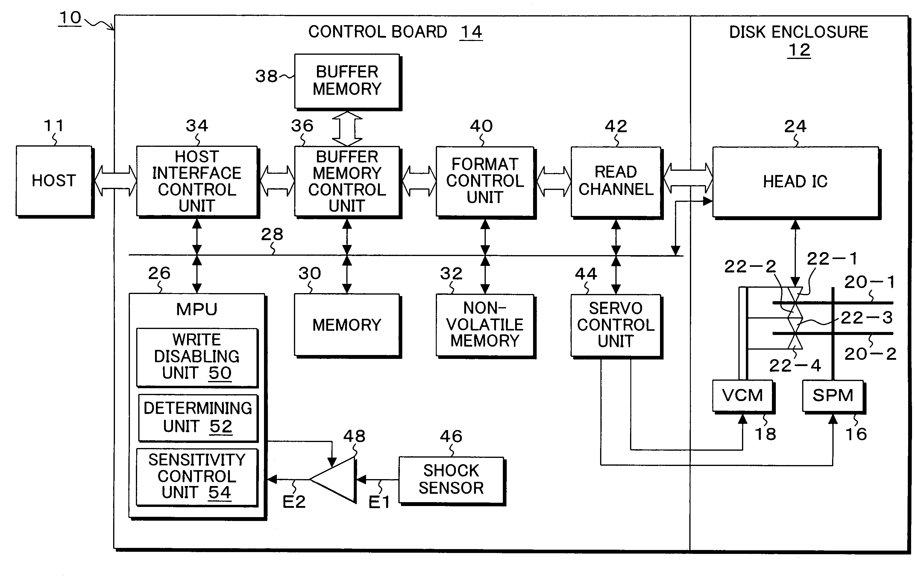
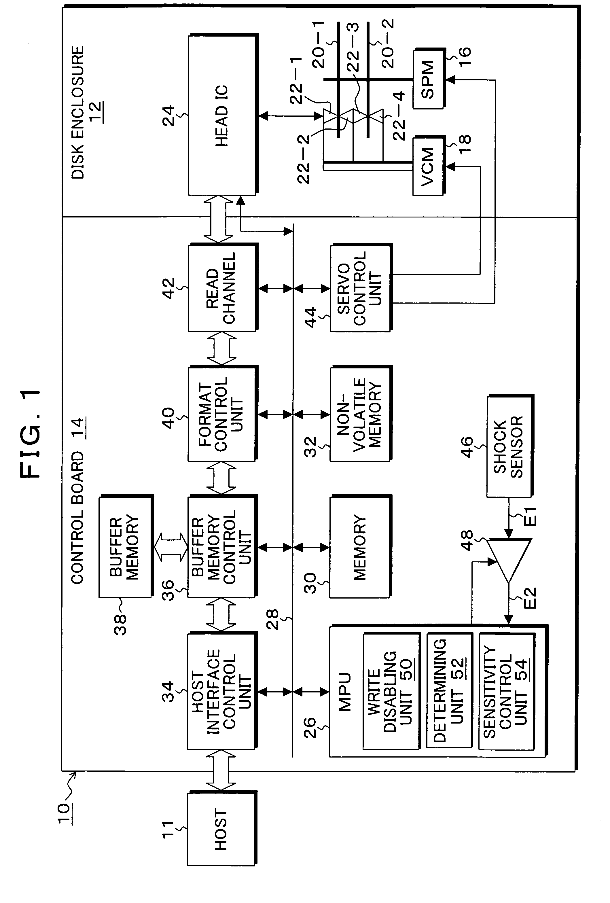
[0045]FIG. 1 is a block diagram of a magnetic disk apparatus as one embodiment of a storage apparatus according to the present invention. In FIG. 1, a magnetic disk apparatus 10 known as a hard disk drive (HDD) is constituted of a disk enclosure 12 and a control board 14. The disk enclosure 12 is provided with a spindle motor 16, and disk media (storage media) 20-1 and 20-2 are mounted on the rotational axis of the spindle motor 16 and rotated at a constant speed. The disk enclosure 12 is provided with a voice coil motor 18, and the voice coil motor 18 mounts heads 22-1 to 22-4 on a tip of an arm of a head actuator to position the head relative to a recording face of the disk media 20-1 and 20-2. A write head and a read head are integrally mounted on the heads 22-1 to 22-4. The heads 22-1 to 22-4 are connected to a head IC 24 through a signal line, and the head IC 24 selects one head by a head select signal based on a write command or read command from a host 11 as a higher-level ap...


PUM

PropertyMeasurementUnit
threshold voltageaaaaaaaaaa
timeaaaaaaaaaa
voltageaaaaaaaaaa

Abstract

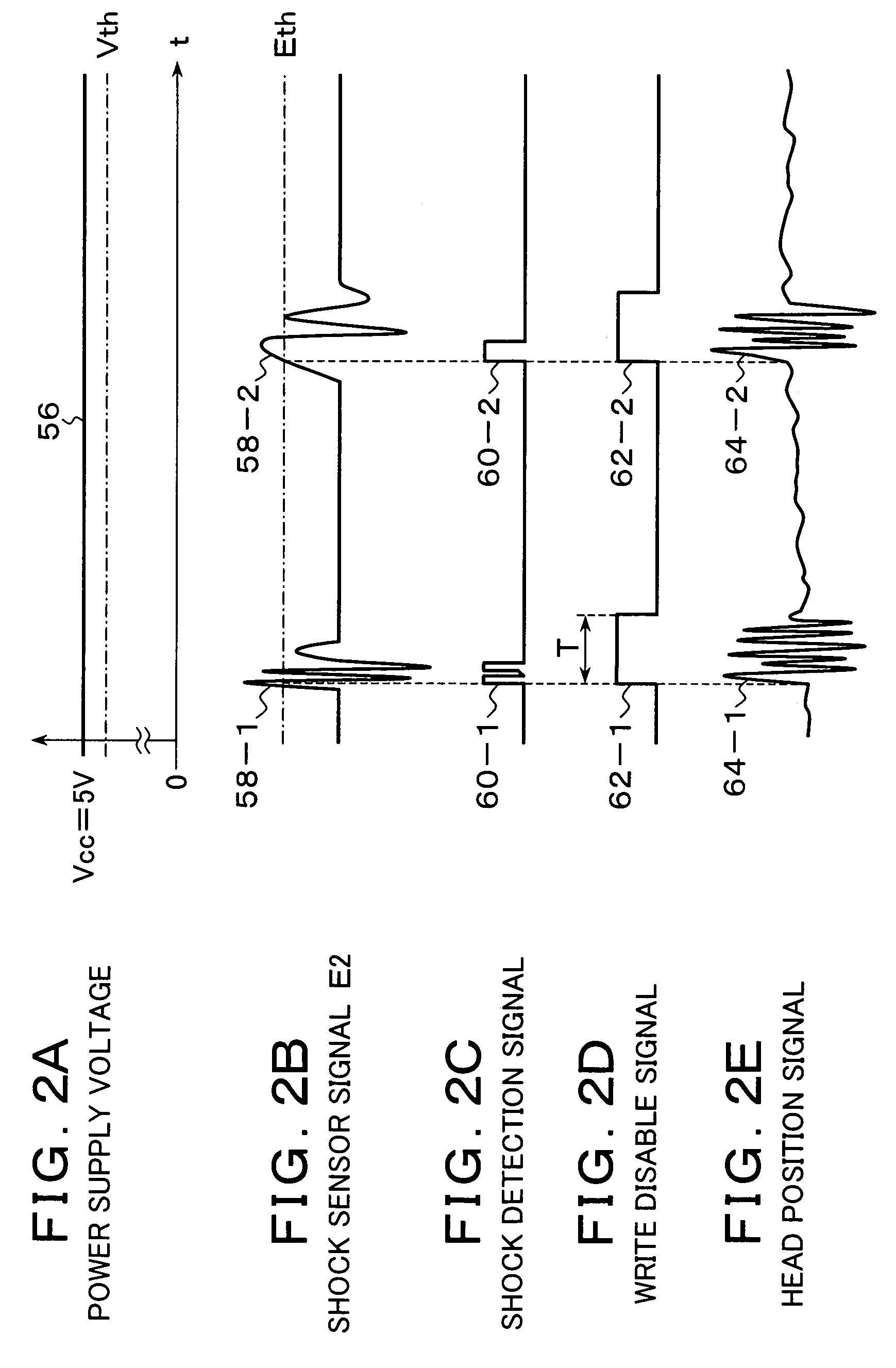
Upon obtaining a detection signal of a shock sensor that detects a shock applied to an apparatus for output, a write disabling unit disables writing by a head on a medium over a predetermined time corresponding to a shock convergence. A determining unit determines, during the write disable, whether an output of the shock sensor is a detection output of the shock sensor due to a shock or an erroneous detection output of the shock sensor due to power supply fluctuations. A sensitivity control unit increases a detection sensitivity of the shock sensor when the determining unit determines that the output is a detection output due to the shock, and decreases the detection sensitivity of the shock sensor and clears the write disable when the determining unit determines that the output is an erroneous detection output due to power supply fluctuations.

Description

[0001]This application is a priority based on prior application No. JP 2005-316488, filed Oct. 31, 2005, in Japan.BACKGROUND OF THE INVENTION[0002]1. Field of the Invention[0003]The present invention is a storage apparatus, such as a magnetic disk apparatus equipped with a shock sensor, and its control method and program and, particularly, to a storage apparatus that protects information stored in a medium by detecting a shock to disable writing, and its control method and program.[0004]2. Description of the Related Arts[0005]Conventionally, as for a storage apparatus, such as a magnetic disk apparatus, a shock sensor is placed in the storage apparatus to determine that a detection output of the shock sensor when a shock is externally applied exceeds a predetermined threshold and disable a writing operation during a predetermined time until an impact by shock converges, thereby achieving protection so that data is prevented from being destroyed by writing onto an adjacent cylinder w...

Claims


Application Information

Patent Timeline
Patent Type & Authority Patents(United States)
IPC IPC(8): G11B19/04
CPCG11B5/5582G11B19/04G11B33/08
Inventor SAITOH, SHUNJISUZUKI, ATSUSHIHARA, TAKESHI
Owner KK TOSHIBA
Learn More