Emergency lighting arrangement with decentralized emergency power supply for an aircraft

a technology for emergency lighting and aircraft, applied in the field of emergency lighting arrangement for aircraft, can solve the problems of increasing the total system weight, reducing the inspection and maintenance effort, and increasing the cost of maintenance and maintenance, so as to reduce the maintenance effort and expenditure

Active Publication Date: 2008-05-27
AIRBUS OPERATIONS GMBH
View PDF22 Cites 18 Cited by
  • Summary
  • Abstract
  • Description
  • Claims
  • Application Information

AI Technical Summary

Benefits of technology

[0007]In view of the above, it is an object of the invention to provide an emergency lighting arrangement for an aircraft, in which the maintenance effort and expenditure are reduced while the system reliability is improved in comparison to the prior art. A further object of the invention is to provide a weight-optimized construction of the arrangement especially for installation thereof in an aircraft. The invention further aims to avoid or overcome the disadvantages of the prior art, and to achieve additional advantages, as apparent from the present specification. The attainment of these objects is, however, not a required limitation of the claimed invention.
[0018]Through the use of capacitors as electrical storage devices, it is possible to completely omit rechargeable batteries, which have a relatively high maintenance requirement. In this regard, the capacitors are essentially maintenance free, which is understood to mean that on average the capacitors require no maintenance over the average operating lifetime of a high capacity commercial passenger transport aircraft. For this reason, in connection with a plurality of emergency lights distributed in an aircraft, it is preferably possible to allocate an individual emergency current source respectively to each emergency light. In other words, each emergency light is individually connected to its own emergency current source, without thereby increasing the overall system maintenance requirement, because the capacitors do not require any maintenance. In this manner, the length of the electrical conductor lines extending between the emergency current source and the light emitting element (or elements) associated therewith can be considerably reduced, which achieves a reduction of the overall system weight and a simplification of the installation. In that regard, the emergency light no longer requires external connections for emergency current supply lines.
[0019]A further advantage is that upon the failure of a given emergency current source, only the single individual emergency light (for example) connected to this particular failed emergency current source will thereby be impaired. In other words, the failure of an emergency current source will no longer impair the operability of many emergency lights, but rather only a single emergency light (or a few emergency lights) connected thereto. Still further, a complicated and expensive cabling arrangement for ensuring the greatest possible widespread emergency illumination in the aircraft can also be avoided.
[0020]Through the use of capacitors instead of rechargeable batteries for the emergency power supply, the invention achieves an overall weight reduction of the emergency lighting system in the vehicle, e.g. particularly the aircraft, in which the emergency lighting system is installed. Furthermore, since each emergency light unit can include a control unit that automatically switches on the light emitting element or elements of the emergency light unit in the event of the failure or lack of power being supplied from the on-board power network, an emergency lighting of the aircraft or other vehicle in the event of an emergency is surely and reliably provided in an automatic manner, without requiring a manual operation or actuation thereof. Also, this function of the emergency light emitting elements, namely the emergency operation upon the failure of the on-board power network, is thereby reliably ensured, which also increases the safety of the passengers. The escape paths are maximally illuminated, which helps to satisfy the requirements for a rapid emergency evacuation.
[0021]Preferably, the storage capacity (and thus the capacitance) of the capacitor in a respective emergency light unit is sufficient to operate the emergency light emitting element or elements of this emergency light unit for at least 300 seconds, or preferably at least 600 seconds. This ensures an adequate emergency lighting duration to enable the safe evacuation or exiting of all passengers from the vehicle, e.g. the aircraft. Preferably, the emergency light emitting elements are designed or adapted to be operated with a voltage lower than that of the normal operating voltage of the on-board power supply network, in order to reduce the storage capacity of the capacitor needed to achieve a certain operating duration of the emergency lighting elements, and thereby also to reduce the dimensions and the weight of the capacitor. For the same reason, the power consumption of the emergency lighting elements is preferably as low as possible while providing the required light output. Also for this reason, the light emission efficiency of the emergency lighting elements should be as high as possible. Preferably, the emergency lighting elements can be light emitting diodes (LEDs).

Problems solved by technology

The rechargeable batteries must be regularly tested and occasionally replaced or exchanged due to their limited operating lifetime, which leads to a considerable inspection and maintenance effort and time expenditure.
A further disadvantage of the conventional arrangement is that the battery-powered emergency current units have a relatively high weight, for example because the batteries have a relatively high ratio of weight to storage capacity.
Furthermore, when a plurality of emergency lights are to be connected to a single emergency current supply unit, this requires a complicated cabling arrangement that adds to the total system weight.

Method used


Image

  • Emergency lighting arrangement with decentralized emergency power supply for an aircraft
  • Emergency lighting arrangement with decentralized emergency power supply for an aircraft
  • Emergency lighting arrangement with decentralized emergency power supply for an aircraft

Examples


Embodiment Construction

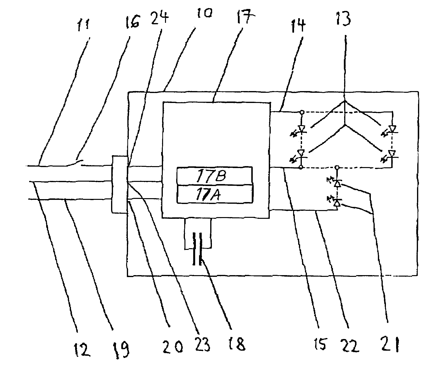
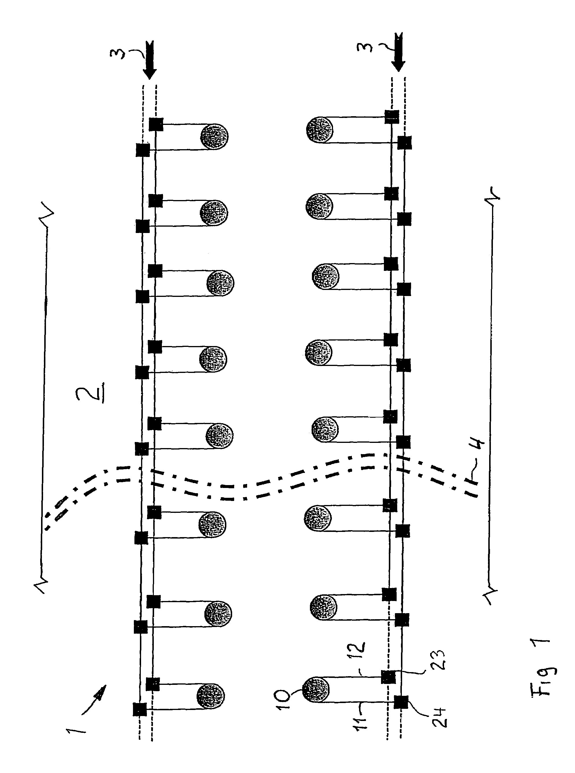
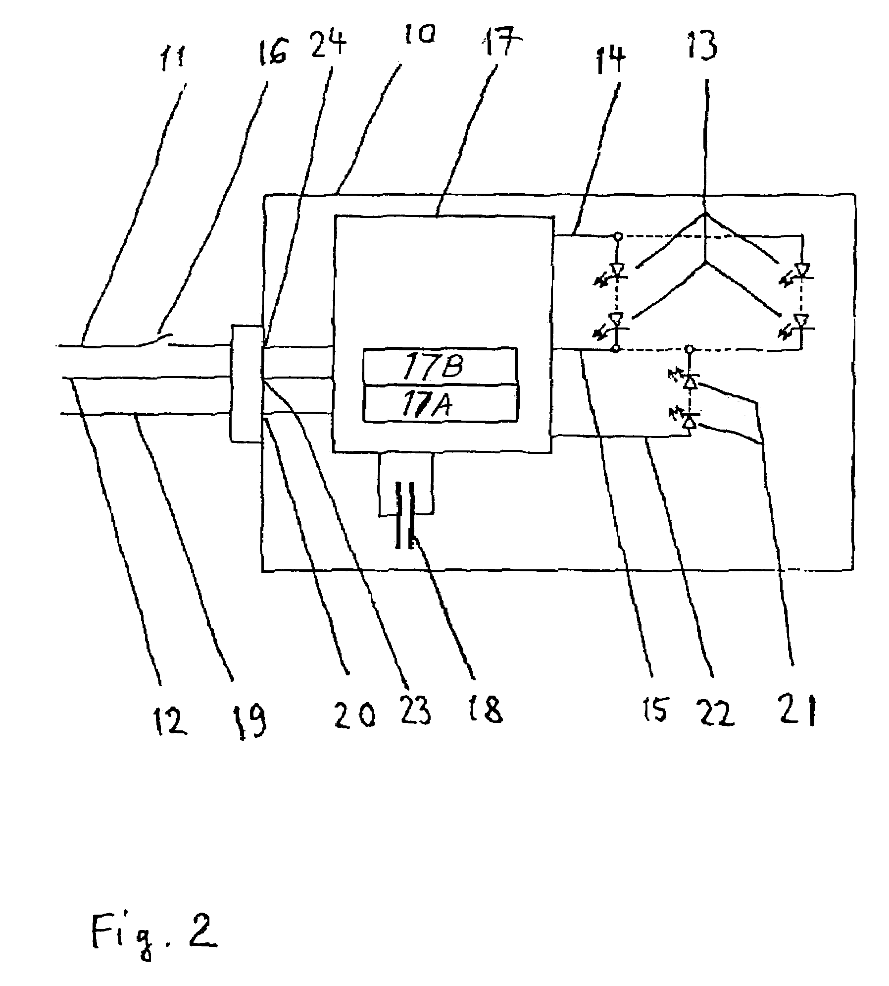
[0027]FIG. 1 schematically shows a first embodiment of an emergency lighting arrangement 1 including a plurality of emergency light units 10 arranged distributed in a passenger cabin 2 of an aircraft or other vehicle, and connected to an on-board electrical power supply network or grid 3. Each emergency light unit 10 is connected via two power supply connection lines 11 and 12 to two respective conductors or power buses of the on-board power supply network 3 via respective plugs, terminals or other connections 23 and 24. In this regard, the power supply connection line 11 may carry the typical on-board operating DC voltage potential, for example 28 V, while the connection line 12 carries the 0 V return potential (DC RTN) for example. The opposite polarity or connection is alternatively possible, as will be discussed below.

[0028]If the on-board power supply network 3 is fully functional and providing electrical power to the connected emergency light units 10, then the light units 10 ...


PUM


Abstract

An emergency lighting arrangement preferably includes plural emergency light units connected to an on-board power supply network of an aircraft, and plural emergency current sources that each include at least one capacitor. Each emergency light unit includes an emergency light emitting element and a control unit that automatically connects the capacitor of the emergency current source to the emergency light emitting element upon the failure of the on-board power supply network. Preferably, the emergency current source including the capacitor is integrated into the emergency light unit. The emergency light unit may further include normal operation light emitting elements selectively connected by the control unit to the on-board power supply network. The control unit switches between normal operation of the normal light emitting elements and charging of the capacitor, and emergency operation in which the capacitor discharges through the emergency light emitting element.

Description

PRIORITY CLAIM[0001]This application is based on and claims the priority under 35 U.S.C. § 119 of German Patent Application 103 61 982.8, filed on Dec. 30, 2003, the entire disclosure of which is incorporated herein by reference.FIELD OF THE INVENTION[0002]The invention relates to an emergency lighting arrangement for an aircraft that comprises at least one emergency light, which includes an emergency lighting (i.e. light emitting) element, and at least one emergency current source for supplying electrical current to the emergency lighting element upon the failure of an on-board electrical power supply network of the aircraft.BACKGROUND INFORMATION[0003]A conventional emergency lighting arrangement in an aircraft includes a number of emergency lights arranged distributed in the aircraft, as well as one or more emergency current supply units having rechargeable batteries that supply electrical current to the emergency lights in the event of a failure of the on-board electrical power ...

Claims


Application Information

Patent Timeline
Patent Type & Authority Patents(United States)
IPC IPC(8): B64D47/06A62B3/00B64D11/00B64D25/00B64D47/02
CPCA62B3/00B64D11/00B64D25/00B64D47/02B64D2011/0038Y02T50/46Y02T50/40
Inventor WISCH, BODOROWOLD, LARS
Owner AIRBUS OPERATIONS GMBH
Why Eureka
Try Eureka