Eureka AIR delivers breakthrough ideas for toughest innovation challenges, trusted by R&D personnel around the world.

Reduction of near field electro-magnetic scattering using high impedance metallization terminations

a technology of metallization termination and high impedance, which is applied in the direction of cross-talk/noise/interference reduction, waveguide type devices, line-transmission details, etc., can solve the problems of unfavorable electro-magnetic field scattering and more likely to interfere with hearing aid devices, so as to reduce the electro-magnetic field scattering, high conductivity area, and high impedance

Active Publication Date: 2008-05-20
SNAPTRACK
View PDF10 Cites 46 Cited by
  • Summary
  • Abstract
  • Description
  • Claims
  • Application Information

AI Technical Summary

Benefits of technology

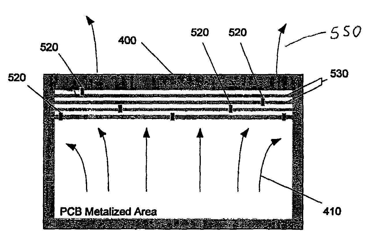
[0004]The present invention uses metallization termination techniques to reduce the electro-magnetic field scattering at the edges of metallized areas including the PCB and metallized housing assemblies. The metallization termination techniques present a gradual transition from high conductivity areas to high impedance areas. The mobile phone antenna illuminates the PCB allowing currents to flow on the PCB. When the currents reach edges of the PCB they flow through a region of increasingly high impedance without reflecting back or scattering.

Problems solved by technology

When the current reaches an edge of a substrate, undesirable scattering of electro-magnetic fields occurs.
The greater the magnitude of scattered fields, the more likely they are to interfere with hearing aid devices.

Method used


Image

  • Reduction of near field electro-magnetic scattering using high impedance metallization terminations
  • Reduction of near field electro-magnetic scattering using high impedance metallization terminations
  • Reduction of near field electro-magnetic scattering using high impedance metallization terminations

Examples


Embodiment Construction

[0012]In a related patent application, a high impedance translucent coating was used to attenuate RF surface waves (electro-magnetic scattering) over a desired region. Such a configuration is effective for attenuating the electric field in the near field region. It also attenuates the generation of surface currents in that region. For improved antenna performance, it may be desirable to allow surface currents to flow on a region of the mobile phone such as the top portion of a flip phone. However, these currents generate scattered electro-magnetic fields at abrupt discontinuities of the PCB and other metallized areas.

[0013]As part of hearing aid compatibility (HAC) assessment, near-field components of electromagnetic fields are measured. These components comprise electric and magnetic fields.

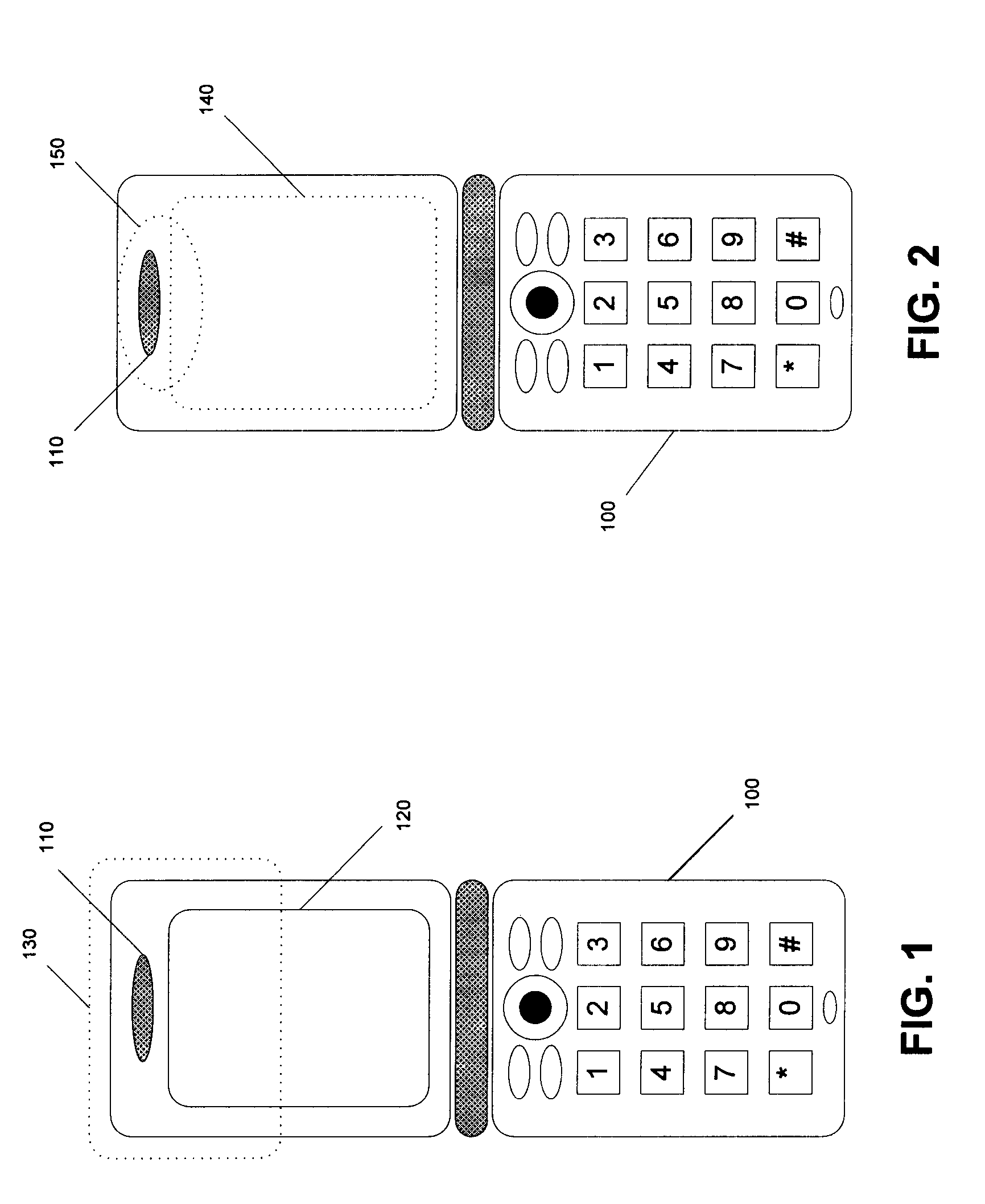
[0014]FIG. 1 is an illustration of a typical flip type mobile phone 100 showing an outline of a near field scan area 130 in the top-flip around the speaker component 110 and partially encompassi...


PUM


Abstract

The present invention uses metallization termination techniques to reduce the electro-magnetic field scattering at the edges of metallized areas. The metallization termination techniques provide a gradual transition from high conductivity areas to high impedance areas. The mobile phone antenna illuminates the PCB allowing currents to flow on the PCB. When the currents reach edges of the PCB they flow through a region of increasingly high impedance without reflecting back or scattering.

Description

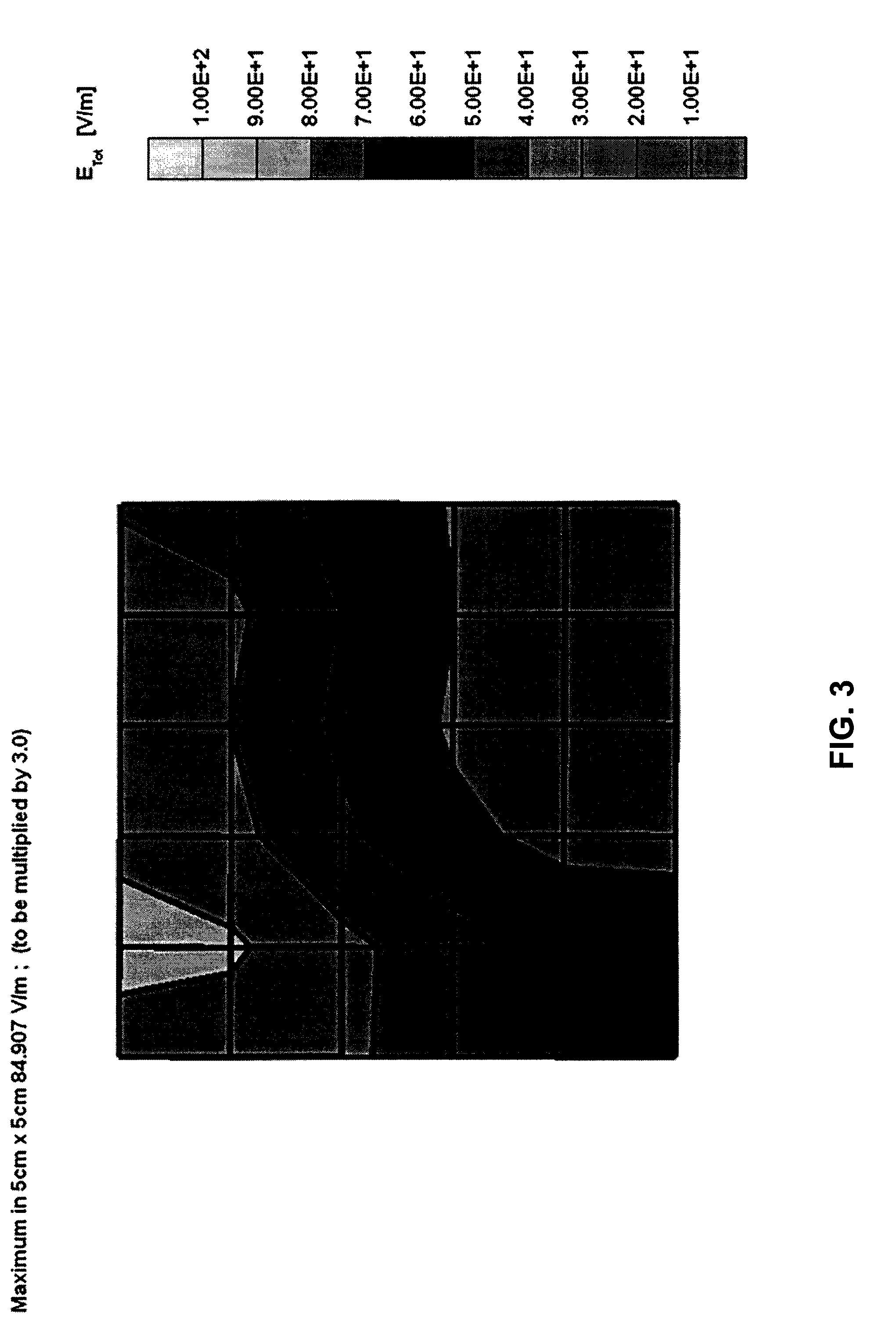
BACKGROUND OF INVENTION[0001]The United States Federal Communications Commission (FCC) is set to enact new regulations in 2005 to improve hearing aid compatibility (HAC) for hearing impaired users of mobile phones. As part of mobile phone HAC assessment, near field components of electro-magnetic fields are measured. The components are comprised of electric and magnetic fields.[0002]FIG. 3 illustrates a typical electric field distribution for a flip-type mobile phone having a near field scan area as shown in FIG. 1 and a PCB outline as shown in FIG. 2. The dominant electric fields tend to occur at abrupt discontinuities of metallization such as at the edges of printed circuit boards (PCBs), shield cans, vibrators, and metallization patterns on the assembly. These discontinuities form concentrated electric currents on the metallic substrates that flow toward the edges of a substrate. When the current reaches an edge of a substrate, undesirable scattering of electro-magnetic fields occ...

Claims


Application Information

Patent Timeline
Patent Type & Authority Patents(United States)
IPC IPC(8): H04B1/10H01P1/00H05K1/02H05K9/00
CPCH05K1/0216H05K1/0231H05K1/0233H05K1/0234H05K9/0039H05K1/0224H04B1/3838H05K1/167H05K2201/093H05K2201/10022H05K2201/1003H05K2201/10446H05K2201/09354
Inventor HAYES, GERARD JAMESVANCE, SCOTT LADELL
Owner SNAPTRACK
Why Eureka
Eureka Blog
Learn More