Methods and apparatus for optical data transmission over standard fiber

a technology of optical data transmission and optical fiber, applied in the field of optical data transmission, can solve the problems of reducing transmission, affecting the overall transmission effect of transmission, and difficult to predict the effect of using various transmission techniques in combination on the overall transmission, so as to reduce power requirements and prolong transmission distances

Active Publication Date: 2008-05-13
AVAGO TECH INT SALES PTE LTD
View PDF1 Cites 8 Cited by
  • Summary
  • Abstract
  • Description
  • Claims
  • Application Information

AI Technical Summary

Benefits of technology

[0011]The use of pre-transmission signal distortion in combination with one or more of the other transmission techniques is also described. Pre-transmission signal distortion may be introduced by controlling amplifying the data signal in a symmetric manner to create a relatively large AC electrical data signal that is then used to control an optical modulator. The large symmetric AC modulation signal causes the modulator to operate in a non-linear region thereby intentionally distorting the data signal to be transmitted prior to transmission over the Standard Single Mode Fiber as an optical signal. This can be easily achieved by shifting the bias voltage away from the quadrature point which is used in conventional modulation schemes. Alternatively, the data signal to be transmitted is subjected to non-linear electrical amplification prior to being used as a modulator input signal. In the embodiment where non-linear electrical...

Problems solved by technology

In theory any distance can be traversed by using an appropriate number of repeater devices and SSMFs, but these devices add complexity and cost to a communication system.
Given the complexity of optical transmission systems it is often difficult to predict the effect of using various transmission techniques in combinati...

Method used


Image

  • Methods and apparatus for optical data transmission over standard fiber
  • Methods and apparatus for optical data transmission over standard fiber
  • Methods and apparatus for optical data transmission over standard fiber

Examples


Embodiment Construction

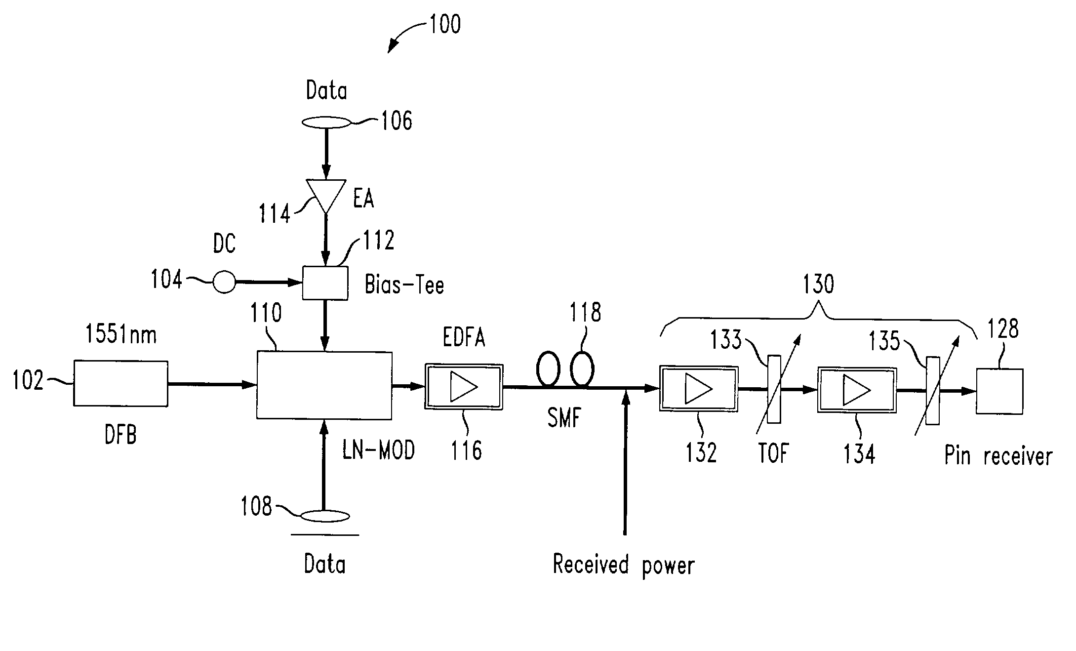
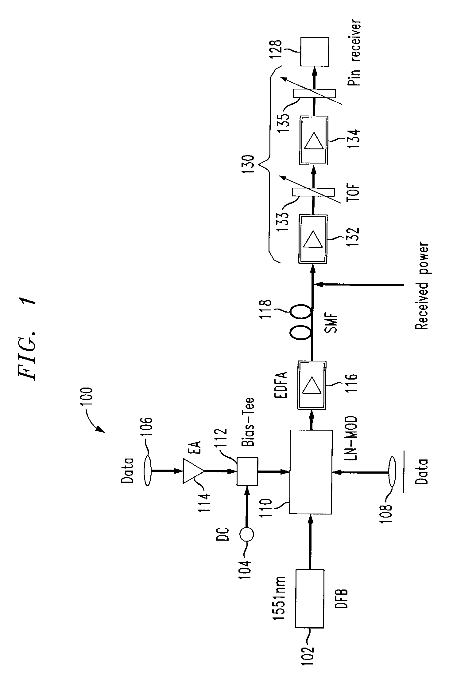
[0039]FIG. 1 illustrates a communication system 100 implemented in accordance with one embodiment of the invention. The communication system 100 includes a distributed feedback diode laser (DFB-DL) 102, a dual-drive LiNbO3, e.g., Nach-Zehnder, modulator 110, electrical signal generators 106, 108, an electrical amplifier (EA) 114, a DC source 104, a bias-tee 112, an erbium doped fiber amplifier (EDFA) 116a, Standard Single Mode Fiber (SSMF) 118, a tunable optical filter (TOF) 130 and a pin receiver 128. The various elements of the system 100 are coupled together as shown in FIG. 1. the TOF 130 is implemented as a two stage device. The TOF 130 includes a first stage comprising a first optical amplifier 132 followed by a first optical filter 133. A second stage comprising a second optical amplifier 134 and a second optical filter 135 follows the first stage. The output of the second optical filter 135 serves as the output of the TOF 130 and is coupled to the input of PIN receiver 128. ...


PUM


Abstract

Methods and apparatus for providing improving optical signal transmission results over standard mode fiber using a combination of negative chirp, low extinction ratio, and self-phase modulation transmission techniques in combination are described. The use of pre-transmission signal distortion in combinations with one or more of the other transmission techniques is also described. Pre-transmission signal distortion may be introduced by controlling a modulator with a large symmetric AC signal which causes the modulator to operation in a non-linear region or, alternatively, by using a relatively small non-symmetric AC signal to drive the modulator. Use of the small non-symmetric signal has the advantage of reduced power requirements. The pre-transmission distortion acts to counter some of the distortion introduced by the transmission of the signal over an optic fiber.

Description

RELATED APPLICATIONS[0001]This application claims the benefit of the filing date of U.S. Provisional Patent Application Ser. No. 60 / 362,589 filed Mar. 4, 2002.FIELD OF THE INVENTION[0002]The present invention is directed to optical data transmission, and more particularly, to methods and apparatus for implementing high-speed optical transmissions over standard optical fiber.BACKGROUND OF THE INVENTION[0003]Communication systems use transmission mediums, e.g., optical fiber, to transmit a signal, e.g., light, which conveys data. The data may correspond to a speech signal or other information. In optical networks Standard Single Mode Fiber (SSMF) is one transmission medium that is used in the art. As data signals are transmitted through SSMF, signal attenuation due to noise and characteristics of the medium, e.g., group-velocity dispersion (GVD), limits the distance a signal can travel. Therefore, one technique used to transmit data across a large distance is to use devices that overc...

Claims


Application Information

Patent Timeline
IPC IPC(8): H04B10/04H04B10/12H04B10/18
CPCH04B10/25137
Inventor YU, JIANJUNKOJIMA, KEISUKECHAND, NARESH
Owner AVAGO TECH INT SALES PTE LTD
Why Eureka
Try Eureka