Voice-controlled surgical lighting assembly

a surgical lighting and voice control technology, applied in the direction of lighting support devices, instruments, applications, etc., can solve the problems of high construction cost of the operation room, large amount of heat, and the need for structural strength of the ceiling and the whole operation room, and achieve the effect of effectively instructing and convenient responsiveness

Inactive Publication Date: 2008-05-13
ELLIS FANT WANDA J
View PDF12 Cites 40 Cited by
  • Summary
  • Abstract
  • Description
  • Claims
  • Application Information

AI Technical Summary

Benefits of technology

[0014]A light-emitting source distally spaced from the strap effectively includes a power supply source electrically coupled to the light-emitting assembly. Such a power supply source is conveniently rechargeable.
[0017]The voice-activated mechanism may include a microphone, a processor and an analog-to-digital converter electrically coupled to the microphone. Such a converter preferably receives an input signal in analog format based upon a user voice command and generates an output signal in digital format for effectively instructing the processor to perform a control logic algorithm responsive to the input signal. A memory may include software instructions for conveniently causing the light-emitting assembly to perform the steps of biasing the motor assembly and advantageously activating the light-emitting source between on and off positions respectively.

Problems solved by technology

Furthermore, because of its very heavy weight, not only the ceiling but also the whole operation room is required to be structurally strong.
As a result, the construction cost of an operation room is high due to this lighting system.
Another problem of the astral lighting system is that it generates a large amount of heat.
This also has increased the construction cost of the operation room.
Also, many prior art devices include manual switches which serve to hinder the sterility of a surgical environment as well as encumbering the user.

Method used


Image

  • Voice-controlled surgical lighting assembly
  • Voice-controlled surgical lighting assembly
  • Voice-controlled surgical lighting assembly

Examples


Embodiment Construction

[0038]The present invention will now be described more fully hereinafter with reference to the accompanying drawings, in which a preferred embodiment of the invention is shown. This invention may, however, be embodied in many different forms and should not be construed as limited to the embodiment set forth herein. Rather, this embodiment is provided so that this application will be thorough and complete, and will fully convey the true scope of the invention to those skilled in the art. Like numbers refer to like elements throughout the figures.

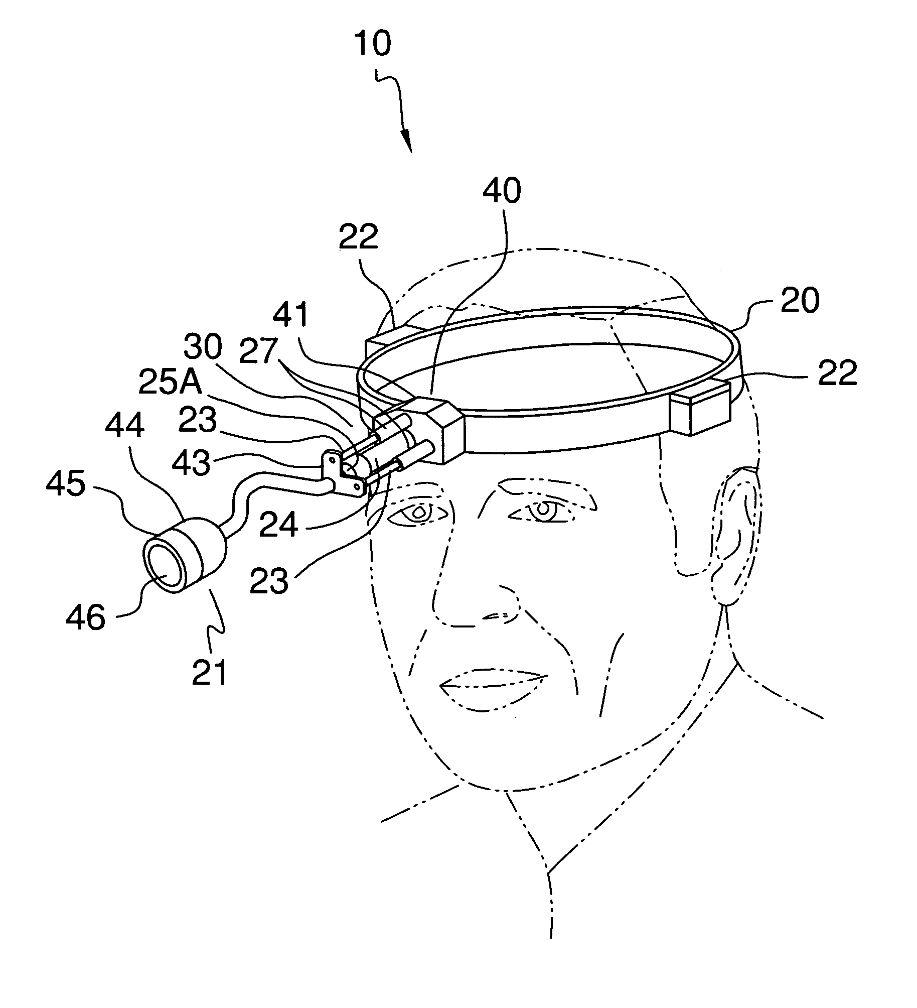
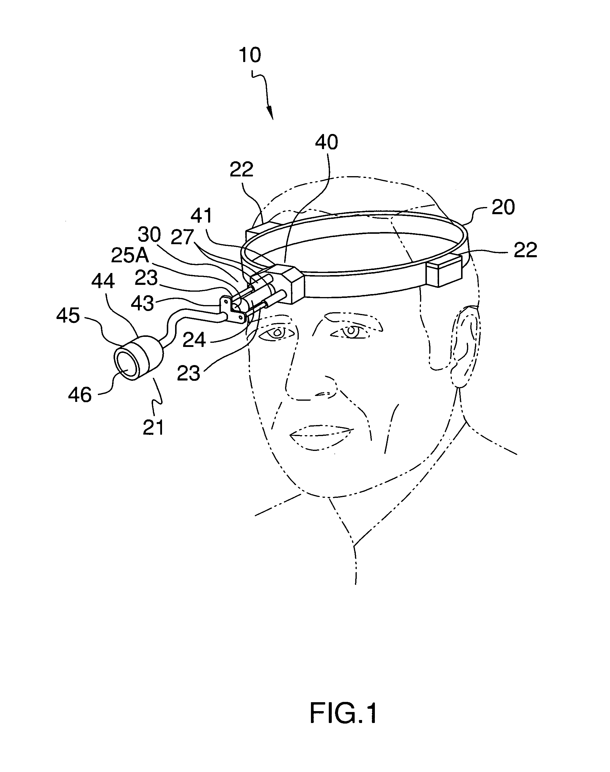
[0039]The assembly of this invention is referred to generally in FIGS. 1-13 by the reference numerals 10, 10′ and 10″ and is intended to provide a voice operated lighting assembly. It should be understood that the assembly 10, 10′ and 10″ may be used to operate many different types of electrical accessories and should not be limited in use only to lights.

[0040]Referring initially to FIGS. 1-4, the light-emitting assembly 10 includes a continu...


PUM


Abstract

The assembly includes a strap adaptable to a variety of positions. Such a strap is placed directly about the user's head. A light-emitting source spaced from the strap includes a power supply source electrically coupled to the light-emitting assembly. Such a power supply source is rechargeable. A voice-activated mechanism for biasing the light-emitting source is defined from the strap so that the light-emitting assembly can be adapted along an x-axis, y-axis and z-axis. A motor assembly is directly and operably conjoined to the voice-activated mechanism and the light-emitting assembly. The voice-activated mechanism cooperates with the light-emitting source and the motor assembly during operating conditions. Such a voice operating mechanism is power-operated. The voice-activated mechanism is conveniently responsive to a user's voice commands in such a manner that the user can selectively operate the motor assembly and the light-emitting source from a remote location.

Description

CROSS REFERENCE TO RELATED APPLICATIONS[0001]Not Applicable.STATEMENT REGARDING FEDERALLY SPONSORED RESEARCH OR DEVELOPMENT[0002]Not Applicable.REFERENCE TO A MICROFICHE APPENDIX[0003]Not Applicable.BACKGROUND OF THE INVENTION[0004]1. Technical Field[0005]This invention relates to lighting assemblies and, more particularly, to a lighting assembly for surgical use that is voice-operated.[0006]2. Prior Art[0007]For a light in an operation room of a hospital, a so-called astral lighting system has been used to illuminate the part of operation with high illuminance without casting shadows there.[0008]An astral lighting system is constructed so that many lamps are embedded in a large dish-like base which is suspended from the ceiling of the operation room. Therefore, for its placement, a large room is needed and the ceiling of the operation room must be adequately high. Furthermore, because of its very heavy weight, not only the ceiling but also the whole operation room is required to be...

Claims


Application Information

Patent Timeline
Patent Type & Authority Patents(United States)
IPC IPC(8): B60Q1/24
CPCA61B19/5202F21L4/04F21L14/00F21V21/145F21V21/15A61B2017/00203A61B2019/262F21L4/08F21V21/084F21V23/0442G10L15/26Y10S362/804A61B2090/502A61B90/30A61B90/35
Inventor ELLIS-FANT, WANDA J.
Owner ELLIS FANT WANDA J
Why Eureka
Try Eureka