Apparatus and method for releaseably joining elements

Inactive Publication Date: 2008-05-06
THE BOEING CO
View PDF23 Cites 15 Cited by
  • Summary
  • Abstract
  • Description
  • Claims
  • Application Information

AI Technical Summary

Benefits of technology

[0010]The apparatus and method for releasably joining first and second elements of the present invention allow a gentle release of the elements by reducing or substantially eliminating the source of the shock experienced by elements that are joined using conventional techniques. The shock experienced by the elements upon release from the apparatus is reduced by substantially eliminating the release of constrained or potential energy stored in the apparatus. As such, there is less risk of damage to sensitive equipment or electronics carried by the elements when utilizing the apparatus and method of the present invention than when utilizing conventional techniques for releasably joining elements. In addition, the elements joined by the apparatus and method of the present invention require less protection because of the reduced risk of damage to sensitive equipment carried by the elements, which can decrease the cost of the elements. Furthermore, the apparatus and method of the present invention can utilize the conventional clampband design, such that minimal changes to a conventional clampband and / or the elements are required when the apparatus and method of the present invention are implemented in a clampband application.
[0014]A loosening element may be located proximate to the retaining member, such as the recessed portion of the retaining member, if applicable. The loosening element may partially release the elements from the retaining member prior to reshaping the reshapeable tube. Partially releasing the elements may further reduce or eliminate any release of constrained energy when the retaining member is deflected to release the elements.
[0017]Thus, the apparatus and method for releasably joining elements of the present invention securely join elements, but also are capable of gently releasing the elements at an appropriate time. The gentle release of the elements is afforded by the design of the retaining member and reshapeable tube, such that constrained or potential energy is not stored in the apparatus and, therefore, not released when a portion of the retaining member is deflected. As such, the elements are protected from the damage caused by the shock created by the release of constrained energy in conventional release techniques. In addition, the design of the retaining member and reshapeable tube match the shape of a conventional clampband, such that the retaining member and reshapeable tube may be substituted for the conventional clampband in applications that utilize such a clampband.

Problems solved by technology

In the aerospace industry, for instance, the elements joined by a clampband are generally heavy and subject to significant forces during movement, particularly during the take-off or launch.
In addition, the satellite and the launch vehicle are subject to significant forces during the launch process due to high inertial loads and acceleration of thrust.
At the time the connector is cut, the sudden release of constrained or potential energy stored in the clampband creates a low frequency shock in the elements due to the structural vibrations at the natural frequencies of elements.
Thus, elements that are heavy and / or that are subject to significant forces during movement, which must be held together temporarily by a clampband, experience a large shock upon clampband separation because of the significant amount of constrained energy that is released when the tightened clampband is separated.
This detonation creates pressure within the tube, which causes the tube to become substantially round.
This technique, however, also creates a release of constrained energy when the tube causes the joint to break, which causes the elements to experience shock similar to that described above.
In addition, this technique does not utilize the conventional clampband assembly, such that the joint may require more time and labor for installation than the conventional clampband assembly, which is typically readily available and utilizes known procedures for installation.
If the elements include or contain equipment that is sensitive to sudden movement, then the shock created upon clampband separation or joint breakage may damage the equipment, particularly if the clampband is tightly attached to the fitting(s) between the elements.
The shock created upon clampband separation or joint breakage due to the release of constrained energy is particularly problematic for satellites, which contain highly sensitive sensors and antennas, in addition to other precision equipment.
The shock may damage the sensitive and expensive electronics of the satellite, which may decrease the effectiveness of the satellite or render the satellite useless.
In addition, in order to prevent the equipment from being damaged due to the clampband separation or joint breakage shock, the equipment must include protection, such as shock absorption means and the like, which increases the cost of the equipment.
In addition, when the shock levels are less than 100 g's between 1,000 and 10,000 Hertz, the risk of failure of less expensive, off-the-shelf type components is reduced, and therefore may be used in the elements that are held together by the clampband, instead of costly components with significant amounts of built in protection to withstand larger shock levels.
As such, even with the nut spinning clampband separation technique, an expensive protection means for the equipment is still required.

Method used


Image

  • Apparatus and method for releaseably joining elements
  • Apparatus and method for releaseably joining elements
  • Apparatus and method for releaseably joining elements

Examples


Embodiment Construction

[0027]The present inventions now will be described more fully hereinafter with reference to the accompanying drawings, in which some, but not all embodiments of the invention are shown. Indeed, these inventions may be embodied in many different forms and should not be construed as limited to the embodiments set forth herein; rather, these embodiments are provided so that this disclosure will satisfy applicable legal requirements. Like numbers refer to like elements throughout.

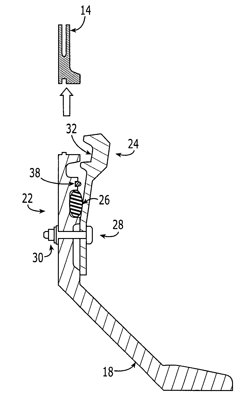
[0028]The apparatus and method for releasably joining first and second elements of the present invention allow a gentle release of the elements by reducing or substantially eliminating the release of constrained or potential energy stored in the apparatus, which is the source of the shock experienced by elements that are joined using conventional techniques. Thus, the present invention is advantageous in many applications, such as clampband applications for releasably joining aerospace elements, because it is a...


PUM


Abstract

The apparatus and method for releasably joining first and second elements according to the present invention include a retaining member mounted to one of the elements and a reshapeable tube near the retaining member. The reshapeable tube has at least two states, an at least partially collapsed state and an at least partially expanded state. As such, the retaining member joins the elements while the reshapeable tube is in the at least partially collapsed state. Furthermore, the retaining member releases the other element while the reshapeable tube is in the at least partially expanded state, which deflects the retaining member. Thus, because components of the apparatus are not broken during the release of the elements, the amount of constrained or potential energy that is released when the retaining member releases the elements is substantially reduced or eliminated, which protects the elements from being damaged during the release.

Description

BACKGROUND OF THE INVENTION[0001]This invention is related to an apparatus and method for releaseably joining elements and, in particular, to an apparatus and method for releaseably joining elements with a clampband that is capable of releasing the elements without damaging the elements by reducing, if not eliminating, the release of constrained energy by the clampband that normally results in shock to the elements when the elements are released.[0002]It is sometimes necessary to join various elements, at least temporarily, by clampbands. A clampband is generally made of one or more interconnected segments separated by respective openings. Typically, a connector, such as a bolt, extends across each opening in the clampband to allow the clampband to be tightened or loosened around the joined elements. The connector that extends across a respective opening may have various forms depending upon the application of the clampband. A commonly used clampband in the aerospace industry is ref...

Claims


Application Information

Patent Timeline
IPC IPC(8): F42B15/38B64G1/64
CPCB64G1/641B64G1/645F42B15/38Y10T403/22Y10T403/7064Y10T403/535B64G1/642B64G1/6455
Inventor CLEVELAND, MARK ALLEN
Owner THE BOEING CO
Why Eureka
Try Eureka