Gate opening and closing apparatus

a technology for opening and closing gates, which is applied in the direction of door/window fittings, power supplies, constructions, etc., can solve the problems of requiring additional real estate, not being a good candidate for access control, and not being aesthetically appealing, so as to eliminate the unsightly appearance of the actuation mechanism, eliminate the negative effects, and simple design and construction

Inactive Publication Date: 2008-05-06
JONES MICHAEL WAYNE
View PDF36 Cites 55 Cited by
  • Summary
  • Abstract
  • Description
  • Claims
  • Application Information

AI Technical Summary

Benefits of technology

[0012]The gate opening and closing apparatus of the present invention addresses the aforementioned needs in the art. The gate opening and closing apparatus has its actuation hardware disposed within the main gate post in order to eliminate the unsightliness of the actuation mechanism and its attendant need for dedicated real estate and to eliminate the negative effects that are occasioned from outside influences such as rain, wind, falling objects, and passersby. The gate opening and closing apparatus is of relatively simple design and construction making the device relatively inexpensive to manufacture, install and maintain.
[0013]The gate opening and closing apparatus of the present invention is comprised of a base plate secured to the ground. A gate is rotatably secured to the base plate via a bearing that is secured to the base plate. A motor is operatively connected to bearing assembly while a male coupling is operatively connected to the motor and a female coupling is mated with the male coupling and is connected to the gate. Upon activation of the motor, the bearing and the male coupling rotate causing the female coupling to rotate, in turn causing the gate to rotate such that upon subsequent activation of the motor, the bearing and the male coupling counterrotate. The motor is connected to the bearing by a rotational plate coupled to the motor, the rotational plate being received by the bearing via an appropriate race. The base plate has a pin that is received within a corresponding slot on the rotational plate in order to act as a physical limit device and also help stabilize travel of the gate. At least one ramp is located on the bearing while a pair of limit switches are located on the rotational plate in order to automatically delimit the activation of the motor.

Problems solved by technology

If appropriate space for such a pocket is unavailable, this type of gate is not a good candidate for access control.
The problem with this type of gate lies in the actuation mechanism.
Not only is this architecture less than aesthetically appealing, it requires additional real estate beyond that required for the gate to be set aside for the actuation device and its connecting hardware.
Additionally, the piston or solenoid rod is exposed to the elements which tends to make the device more prone to failure and therefore such devices require relatively frequent maintenance in order to keep such devices properly operational.
Furthermore, as the piston or solenoid rod is in an extended position whenever the gate is closed, the piston or rod can be bumped, nicked or otherwise jarred when in this position rendering the piston or rod unable to properly retract thereby preventing the gate from being opened and requiring a service call to repair the gate.
Such rod or piston damage can be the result of passersby, falling objects such as a tree limb, or by wind loading.
In any event, the users are inconvenienced by the lack of operability of the gate and the attendant repair costs.
However, the problem with such prior art devices is that they are unduly complex in design and construction making such devices relatively expensive to manufacture and maintain.

Method used


Image

  • Gate opening and closing apparatus
  • Gate opening and closing apparatus
  • Gate opening and closing apparatus

Examples


Embodiment Construction

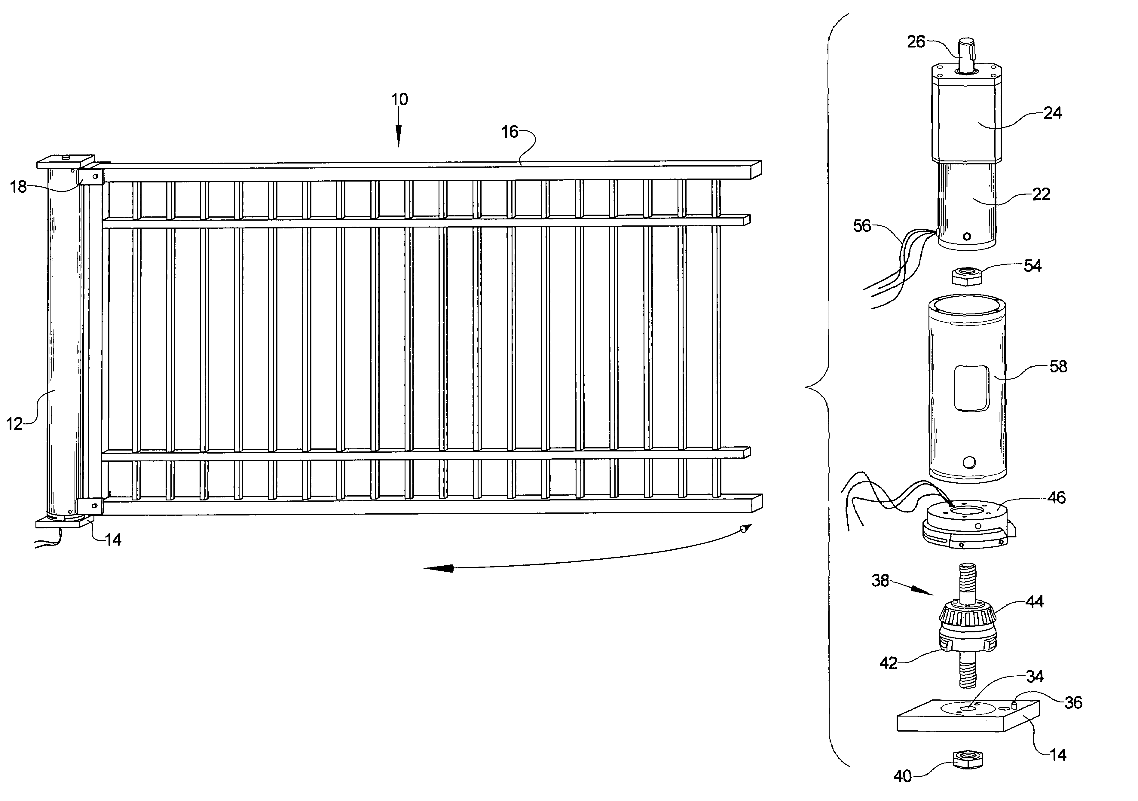
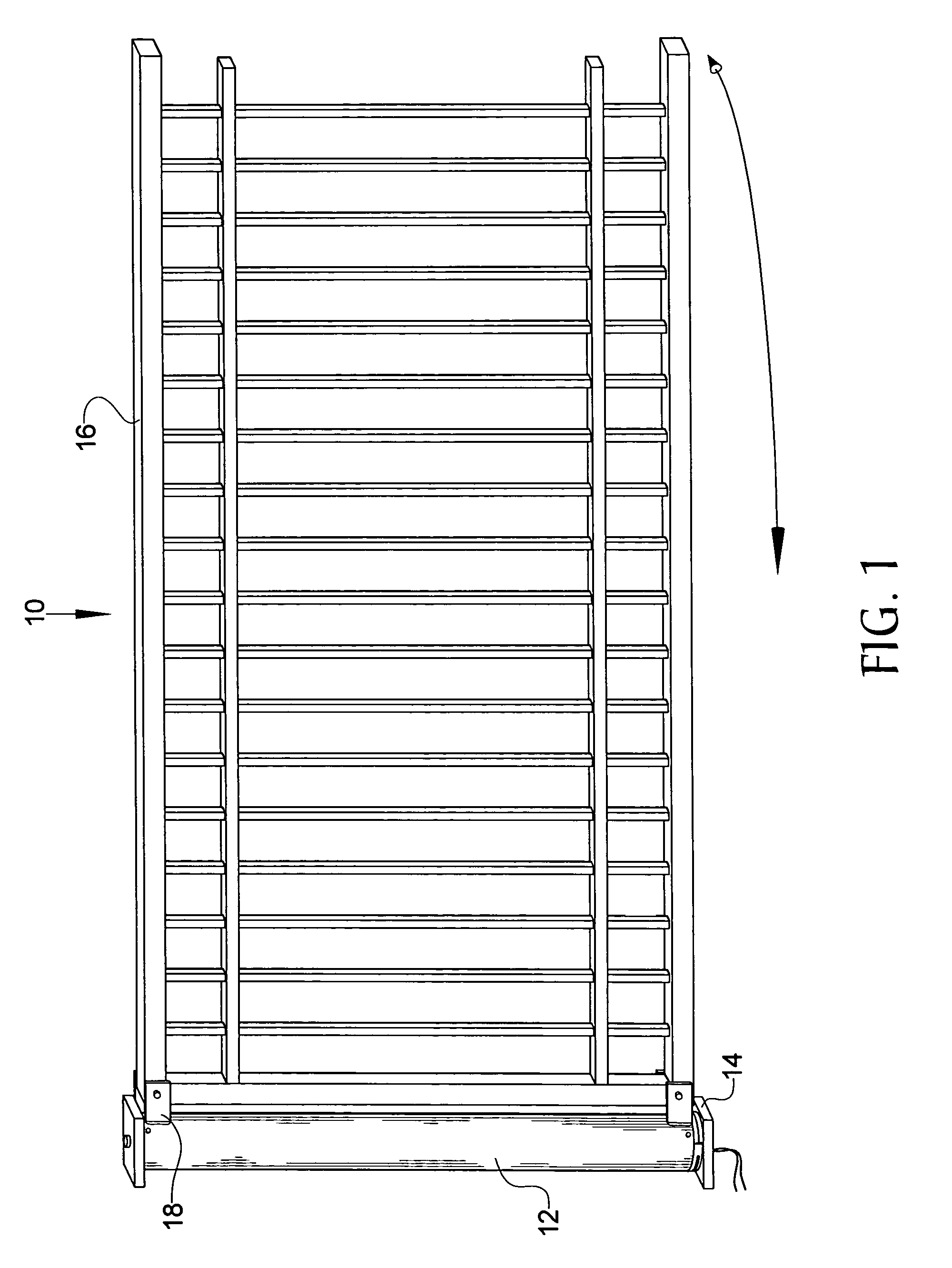
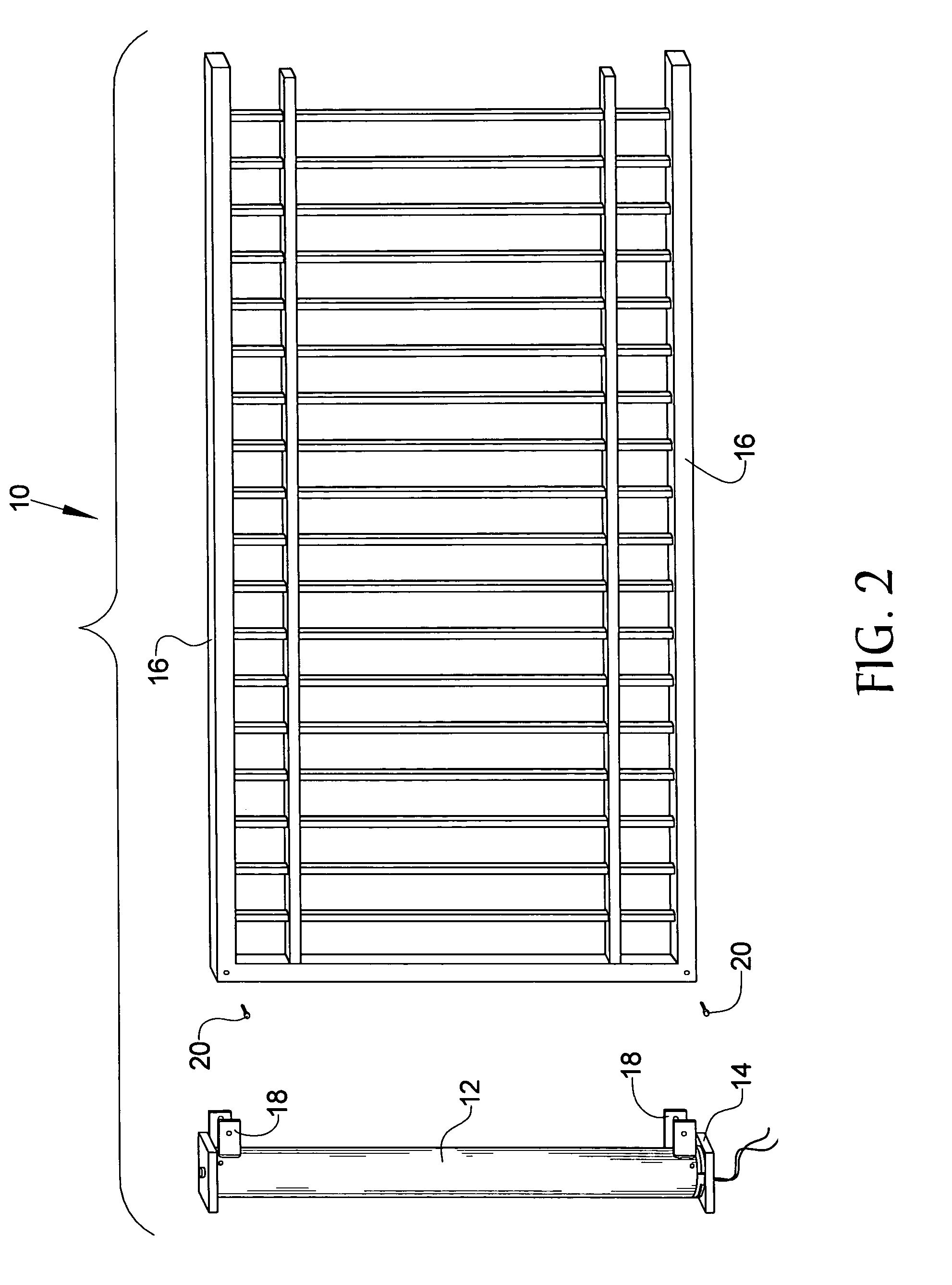
[0022]Referring now to the drawings, it is seen that the gate opening and closing apparatus of the present invention, generally denoted by reference numeral 10, is comprised of a post housing 12 that is secured rotatably connected to a base plate 14. The base plate 14 is secured to the ground in any appropriate fashion. A gate 16 is secured to the post housing 12 by appropriate brackets 18 located on the post housing 12 with pins 20 passing through the gate 16 and the and the brackets 18 for securing the gate thereto. The gate 16 is of any appropriate design such as the illustrated post gate, a lattice gate, etc. The gate 16 pivots with respect to the base plate 14 in order to allow the gate 16 to articulate between an open position allowing ingress and egress through the gate 16 and a closed position whereby ingress and egress through the gate is prevented.

[0023]As seen, rotation of the gate 16 with respect to the base plate 14 is accomplished by a motor assembly. Specifically, a m...


PUM


Abstract

A gate opener has a gate that rotates between an open and a closed position in order to allow or retard ingress and egress through the gate. A plate is secured to the ground while a motor is secured to a post of the gate and is rotatably secured to the plate. Activation of the motor causes the post to rotate and thereby swing the gate open. Subsequent activation of the motor causes the post to counterrotate and thereby swing the gate closed. Appropriate limit switches delimit the arc of travel of the gate.

Description

BACKGROUND OF THE INVENTION[0001]1. Field of the Invention[0002]The present invention relates to an apparatus that automatically opens and closes a rotating gate assembly.[0003]2. Background of the Prior Art[0004]Gates are popular access control devices that help restrict vehicular and pedestrian traffic to a wide array of locations where control of such traffic is desired. Apartment complexes, houses, ranches, and various work sites are typical locations where gates are oftentimes found. Access control gates come in one of two broad categories.[0005]Some gates are manual in that the gate must be opened and closed manually by an operator. A user opens the gate in order to allow a vehicle or a person to pass through the gate and thereafter closes the gate in order to again restrict access therethrough. Such gates are typically found in relatively remote locations, such as a side entrance to a ranch, wherein the frequency of ingress and egress through the gate is relatively sparse and...

Claims


Application Information

Patent Timeline
IPC IPC(8): E05F15/02
CPCE05F15/614E05Y2201/434E05Y2800/262E05Y2800/28E05Y2900/40E05Y2201/224E05Y2400/324E05Y2400/354E05Y2201/216
Inventor JONES, MICHAEL WAYNE
Owner JONES MICHAEL WAYNE
Why Eureka
Try Eureka