
Image processing apparatus for selectively storing specific regions of an image

a processing apparatus and image technology, applied in image enhancement, distance measurement, instruments, etc., can solve the problems of inherently occurring an optical axis misalignment in the stereo camera, the memory capacity needed becomes large, and the cost of memory is difficult to reduce, so as to reduce the cost of the apparatus, increase the processing speed of the cpu, and reduce the amount of data

Inactive Publication Date: 2008-04-29
FUJITSU GENERAL LTD
View PDF28 Cites 12 Cited by
  • Summary
  • Abstract
  • Description
  • Claims
  • Application Information

AI Technical Summary

Benefits of technology

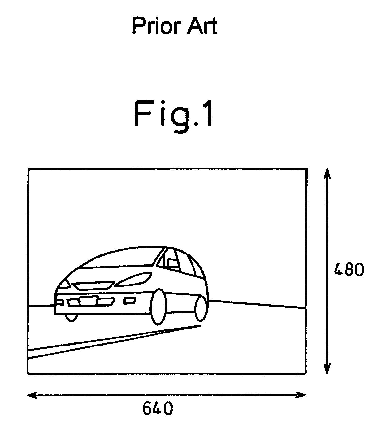
[0017]In an image processing apparatus that captures an image of the road condition ahead or to the rear by means of a video camera and measures the distance to the vehicle ahead by processing the thus captured image, the apparatus performs mathematical operations based on the input signal from the video camera. At this time, the signal from the video camera must be temporarily stored in a memory. In this case, a memory having a large capacity exceeding 2M bits is needed to store, for example, an entire image area of 640×480 (pixels)×8 (bits).
[0018]A low-cost apparatus, however, can only afford a memory of a relatively small capacity, and in view of this, in the present invention the minimum necessary area is selected from the video camera signal and stored in the memory.
[0019]By storing only the area necessary for image processing in the memory, the cost of the apparatus can be reduced while maintaining the necessary performance.
[0020]As one application example, if the apparatus is used to correct the optical axis misalignment of a stereo camera, an advantageous effect of being able to increase the processing speed of the CPU can be obtained.
[0021]Furthermore, according to the present invention, high-density pixel data can be taken from a certain range of the image, and relatively low-density pixel data from the remaining range, for storing in the memory. Since an image can be obtained by switching between these ranges, only the necessary data can be selected and stored in the memory. This serves to reduce the amount of data to be stored in the memory according to the needs without degrading image quality. As a result, the size and cost of the image processing apparatus can be reduced by reducing the required memory capacity of the apparatus.

Problems solved by technology

In the above image processing apparatus, since the amount of data obtained by A / D converting the image signal supplied from the video camera is very large, the memory capacity needed also becomes large, making it difficult to reduce the cost of the memory (a first problem).
There is also the following problem, which is associated with the video camera forming part of the image processing apparatus.
That is, there inherently occurs an optical axis misalignment in the stereo camera constituting the video camera.
This method has been impractical as it takes an enormous amount of time and labor.
This, however, imposes a greater burden on the CPU, and the image processing speed becomes slow (a second problem).

Method used


Image

  • Image processing apparatus for selectively storing specific regions of an image
  • Image processing apparatus for selectively storing specific regions of an image
  • Image processing apparatus for selectively storing specific regions of an image

Examples


Embodiment Construction

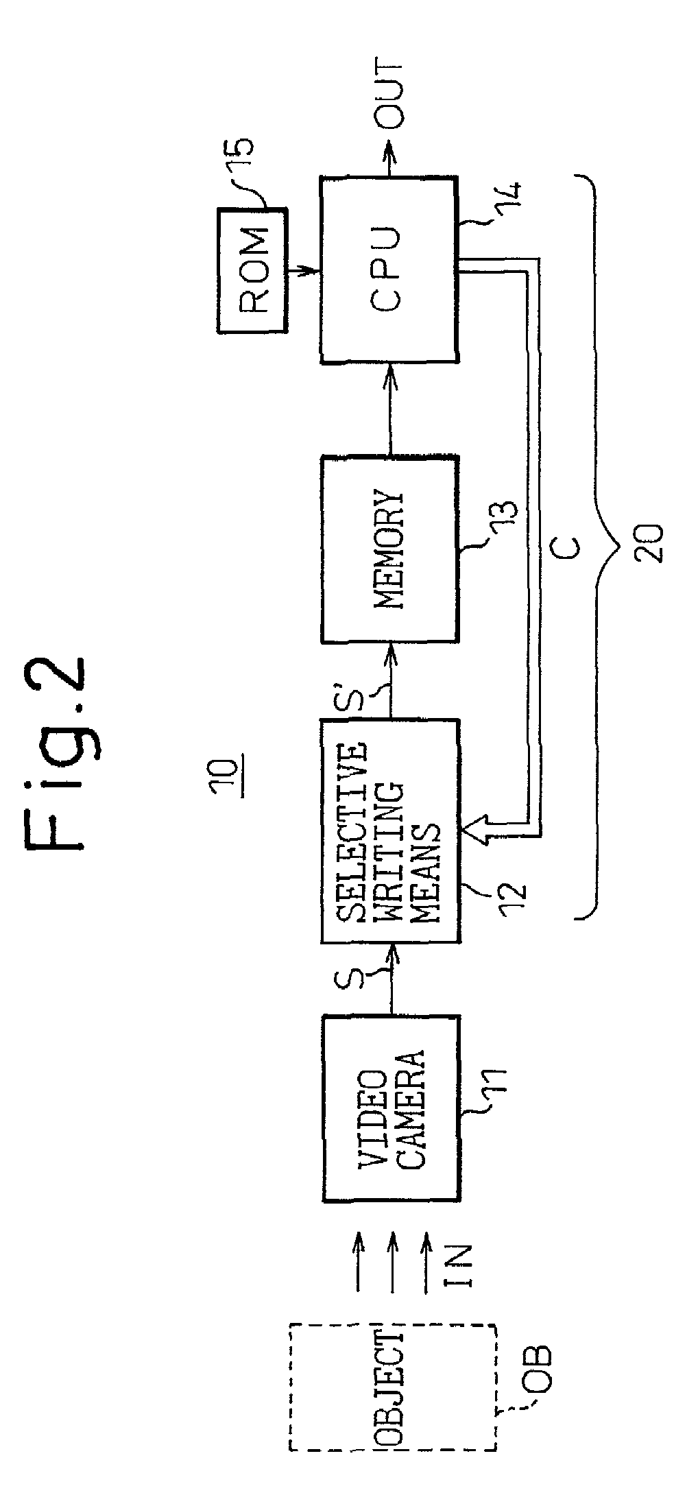
[0041]FIG. 2 is a block diagram showing the basic configuration of the present invention.

[0042]As shown, the image processing apparatus subsumed under the present invention comprises a video camera 11 for capturing an image of an object OB, a memory 13 for storing an image signal S supplied from the video camera 11, and a CPU 14 for performing prescribed processing on the image signal S read out of the memory 13. Reference numeral 20 is a computing processor containing the memory 13, CPU 14, and their attendant circuitry (seeFIG. 3).

[0043]The notable feature of the present invention is the provision of a selective writing means 12 which is placed between the video camera 11 and the memory 13.

[0044]The selective writing means 12 performs a selective write operation by which only a designated portion of the image signal S from the video camera 11 is selected in accordance with a select command C issued from the CPU 13 and only the selected image signal S′ is written into the memory 13...


PUM


Abstract

The invention provides an image processing apparatus that can reduce the memory capacity of a memory forming part of the image processing apparatus and can correct the optical axis misalignment of a video camera in a simple manner. The image processing apparatus 10, which comprises a video camera 11, a memory 13 for storing an image signal supplied from the video camera, and a CPU 14 for performing prescribed processing on the image signal read out of the memory, includes a selective writing means 12 for selecting only a designated portion of the image signal in accordance with a select command C from the CPU, and for writing only the selected portion as a selected image signal S′ into the memory 13. The image processing apparatus further includes a switching means for selecting the pixel data to be stored in the memory by switching between high-density pixel data covering a designated range centralized in a horizontal direction of the image and relatively low-density pixel data covering a full image range. The switching means is capable of switching in accordance with vehicle speed.

Description

CROSS-REFERENCE TO RELATED APPLICATION[0001]This application claims priority of Japanese patent Application No. 2000-279852, filed on Sep. 14, 2000, and Japanese patent Application No. 2000-339487, filed on Nov. 7, 2000.BACKGROUND OF THE INVENTION[0002]1. Field of the Invention[0003]The present invention relates to an image processing apparatus for detecting lane marks, vehicles, or the like by processing an image of the road ahead captured by an onboard video camera mounted in a suitable position such as the position of the rearview mirror.[0004]2. Description of the Related Art[0005]A video camera mounted in a vehicle captures an image of the road ahead of or behind the vehicle, and an image processing apparatus processes the captured image data and detects vehicles, white lines, etc. on the road ahead to control vehicle-to-vehicle distance, etc.[0006]Such an image processing apparatus can be used to issue an audible alarm to the driver when the distance to the vehicle ahead has b...

Claims


Application Information

Patent Timeline
Patent Type & Authority Patents(United States)
IPC IPC(8): H04N5/235B60R1/00G01C3/00G06T7/00H04N7/26H04N7/46H04N13/239
CPCB60R1/00H04N19/59G06T7/0022H04N13/0239H04N13/0296H04N19/17G01C3/00B60R2300/105B60R2300/107B60R2300/207B60R2300/30B60R2300/804G06T2207/10012H04N2013/0081G06T7/97H04N13/296H04N13/239G06V20/58
Inventor YAMADA, MASAHIRO
Owner FUJITSU GENERAL LTD
Learn More