
High density dual helical gear and method for manufacture thereof

a dual-helical gear, high density technology, applied in mechanical equipment, transportation and packaging, layered products, etc., can solve the problems of difficult axial direction accuracy, difficult to obtain accurate dimensions, and long process time to fully densify the gear. , to achieve the effect of high density, low cost and superior strength

Active Publication Date: 2008-04-29
KEYSTONE INVESTMENT CORP
View PDF7 Cites 8 Cited by
  • Summary
  • Abstract
  • Description
  • Claims
  • Application Information

AI Technical Summary

Benefits of technology

[0013]The present invention relates to a low cost technique for manufacturing dual helical gears, such as herringbone gears, from powder metals. The dual helical gears made by this technique are of high density (greater than 92% of theoretical density) and offer superior strength.

Problems solved by technology

A disadvantage of the method employed by Goodwin can be that when the preform is impacted a lot of flashing can result as the preform is forced into the shape of the helical gear and the metal passes through the gap of the unprofiled punch and the profile of the teeth.
A disadvantage with isostatic forming is that it can take much longer for the process to fully densify the gear.
In hot forming, enormous amounts of pressure can be generated in an instant by impacting the gear axially.
Also, for example, obtaining accurate dimensions in the axial direction can be difficult when using isostatic pressure forming.
Thus, the axial dimension can be difficult to accurately control.
Moreover, besides controlling the length of the gear, the lack of control over the axial dimension can also make it more difficult to fully densify the gear.
This is because without control over the axial dimension, the gear can experience some undesirable axial expansion in addition to the radial expansion.
However, in operation helical gears also create an axial thrust which may have to be absorbed by the bearings if same are employed to carry the gear.
Relatively expensive bearings such as thrust bearings are normally employed to absorb such axial forces.
Herringbone gears, however, requiring complex machine tools and are difficult and costly to manufacture.
Consequently, the cost of herringbone gears is quite high.
In fact, though herringbone gears are often preferred in certain mechanical applications, cost has historically prevented their widespread utilization and lesser desirable gears have been employed in their place.
Since it is difficult and costly to manufacture dual helical gears such as herringbone gears utilizing conventional technology, the advantages of manufacturing such gears by compacting and sintering a powder metal are readily apparent.
However, the gears made by the powder metal technique of Hinzmann are not of high density.

Method used


Image

  • High density dual helical gear and method for manufacture thereof
  • High density dual helical gear and method for manufacture thereof
  • High density dual helical gear and method for manufacture thereof

Examples


Embodiment Construction

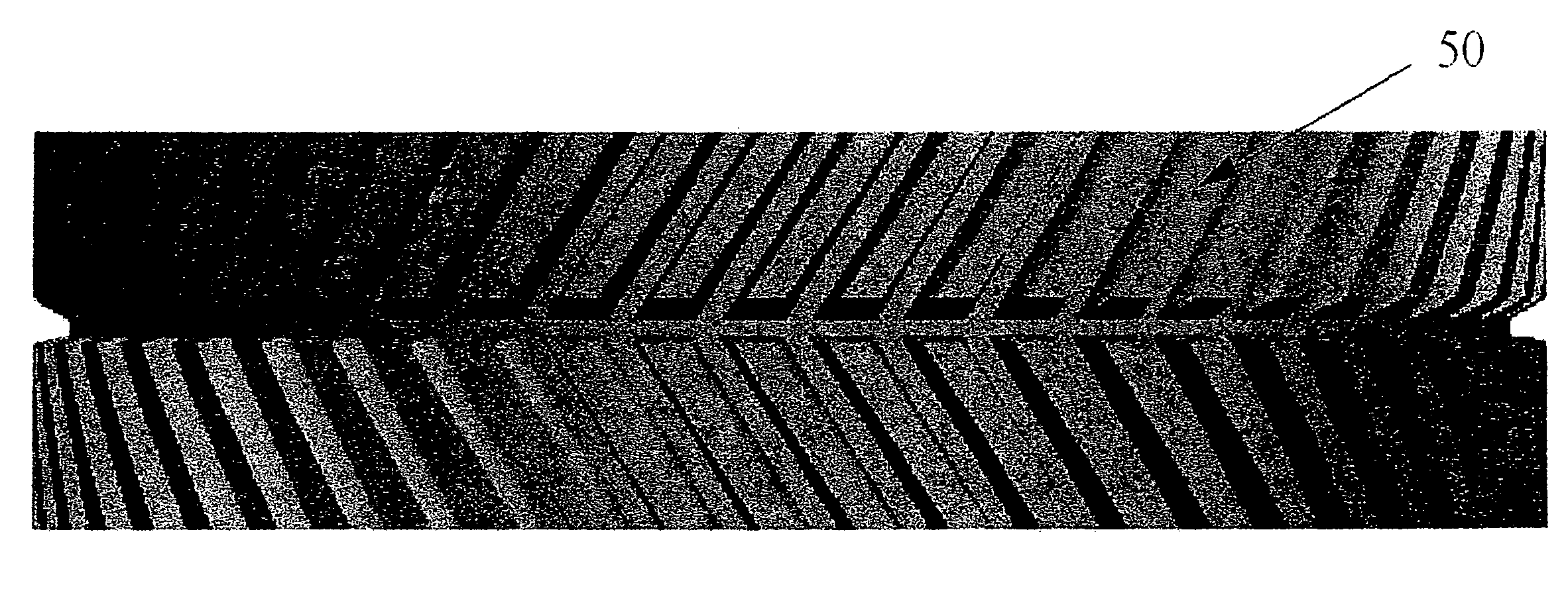
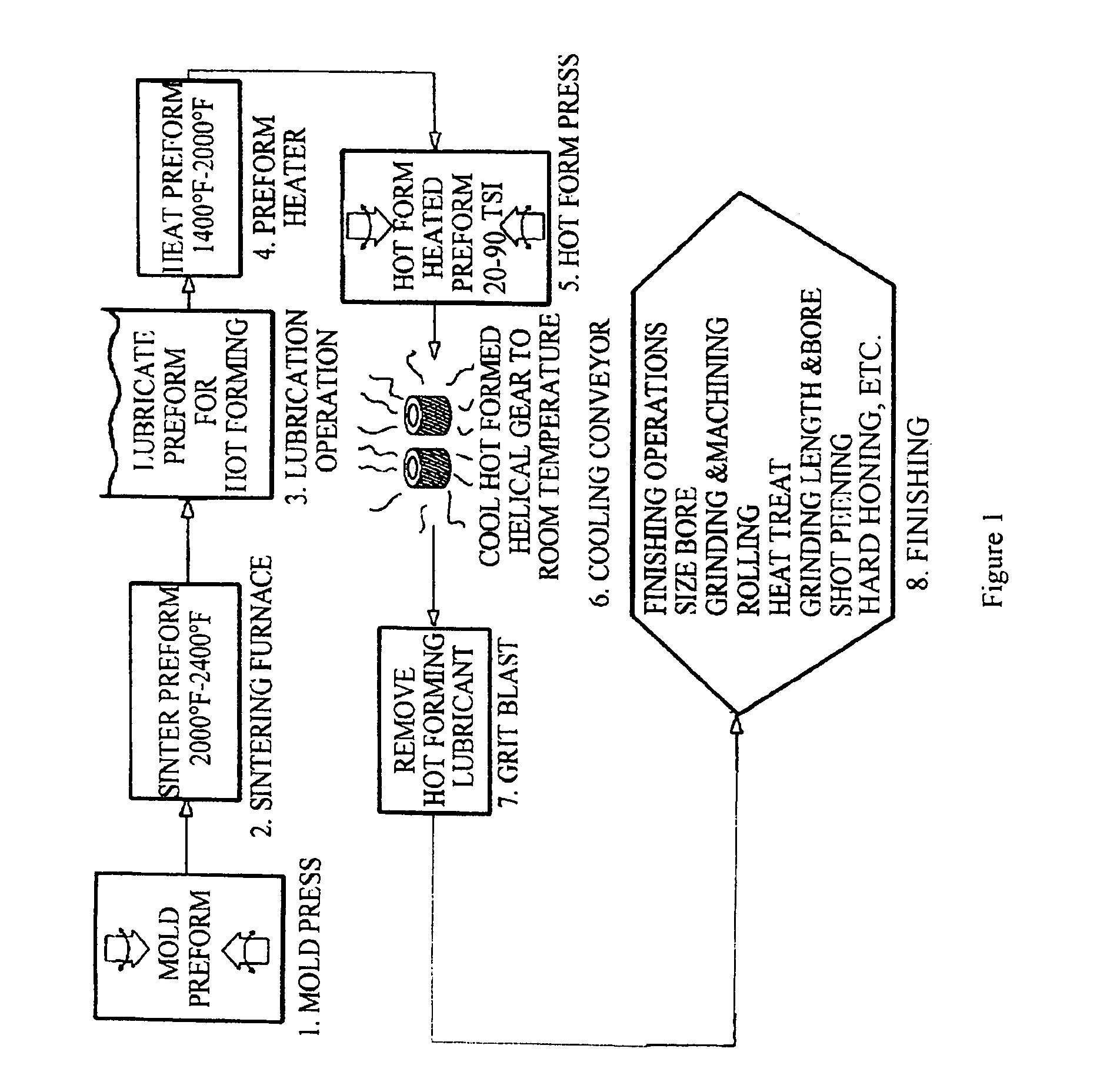
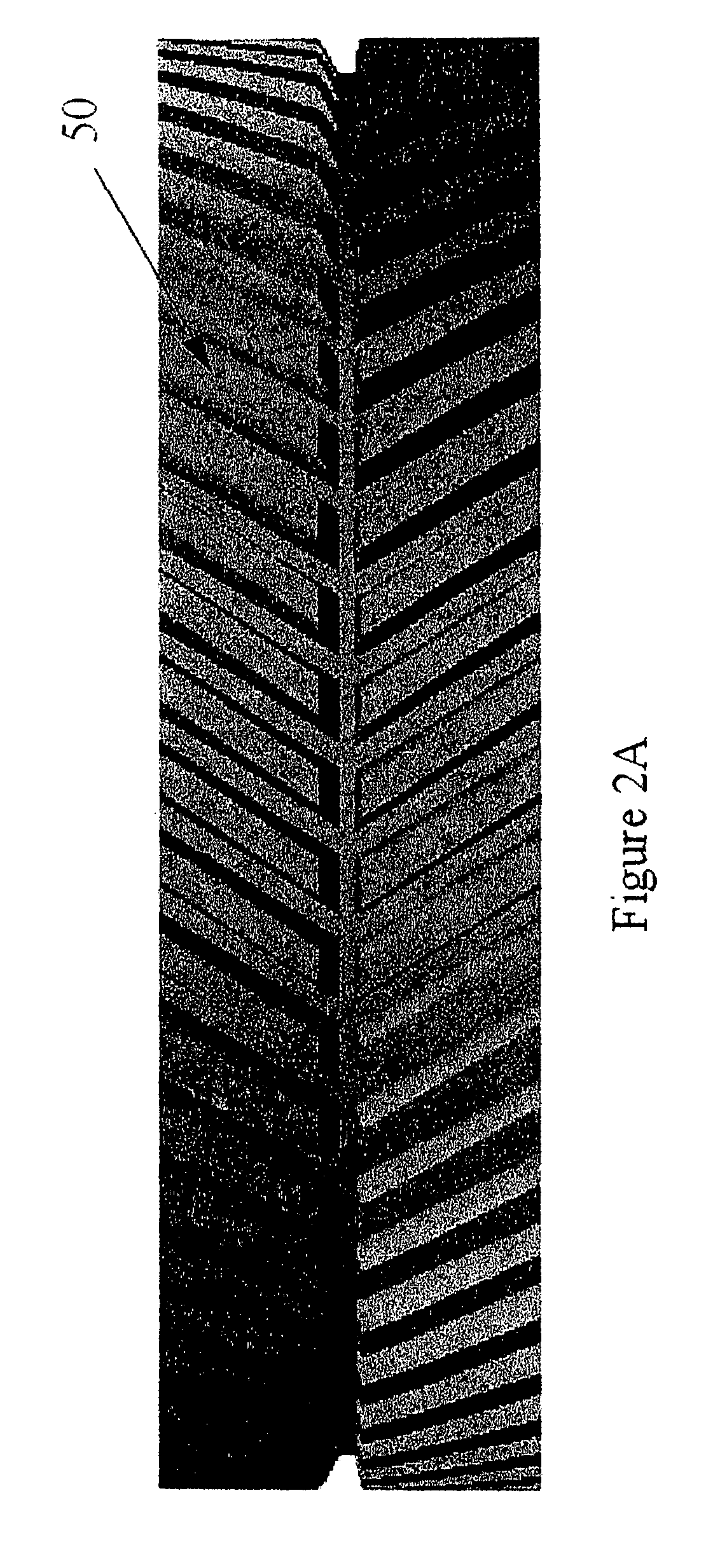
[0037]The present invention will now be described in terms of a method for forming dual helical metal gears and is particularly useful for manufacturing herringbone gears. It should be understood that the Figures and descriptions of the present invention have been simplified to illustrate elements that are relevant for a clear understanding of the present invention, while eliminating, for purposes of clarity, other elements and / or descriptions that are well-known to those skilled in the art. Those of ordinary skill in the art will recognize that other elements may be desirable in order to implement the present invention. However, because such elements are well known in the art, and because they do not facilitate a better understanding of the present invention, a discussion of such elements is not provided herein. Various aspects of the invention are presented in FIGS. 1-6 which are not drawn to scale and in which like components are numbered alike.

[0038]FIG. 1 is directed to one emb...


PUM

PropertyMeasurementUnit
Fractionaaaaaaaaaa
Fractionaaaaaaaaaa
Fractionaaaaaaaaaa

Abstract

The present invention relates to a low cost technique for manufacturing dual helical gears, such as herringbone gears, from powder metals. The dual helical gears made by this technique are of high density (greater than 92% of theoretical density) and offer superior strength. The present invention more specifically discloses a forged metal herringbone gear which is comprised of a body and a plurality of teeth wherein the metal has a density of greater than 92% of theoretical and wherein the grain in the teeth is one range higher on the ASTM E 112 grain size chart than the grain in the body of the gear. The present invention also discloses a method for manufacturing a high density forged dual helical gear.

Description

[0001]This application claims the benefit of U.S. Provisional Patent Application Ser. No. 60 / 587,740, filed on Jul. 14, 2004 (now abandoned) and incorporates the teachings thereof herein by reference in their entirety.BACKGROUND OF THE INVENTION[0002]The production of powdered metal articles, including gears, is well-known in the art. One can use a single type of powdered metal or, depending upon the properties desired, one can use different types metal powders blended together. The powder is disposed in a mold cavity which can be a simple cylindrical preform or may have the profile of the finished product. Then, pressure is applied to create the preform. The preform can then be removed and sintered to produce the part. Where a cylindrical preform is used, the preform is placed in another mold and more pressure is applied to form an article having the desired shape. This new preform can then be sintered.[0003]Apparatus for forming helical gears are also known in the art wherein port...

Claims


Application Information

Patent Timeline
IPC IPC(8): B22F3/17B22F5/08B23P15/14
CPCB21K1/30B21K1/305B22F3/17B22F5/085B23P15/14B22F2998/00Y10T428/12993F16H55/06Y10T428/12014Y10T428/12396Y10T428/12201B22F3/03
Inventor ANDERSON, GARY L.
Owner KEYSTONE INVESTMENT CORP
Learn More