
External operating handle mechanism for mold cased circuit breaker

a technology of operating handle and circuit breaker, which is applied in the direction of contact mechanism, protective switch operation/release mechanism, protective switch details, etc., can solve the problems of unreasonable force applied to the handle lever b>13/b> or resin components, failure to successfully complete reset operation, etc., and achieve efficient and accurate transfer of strokes.

Active Publication Date: 2008-04-22
LG IND SYST CO LTD
View PDF5 Cites 12 Cited by
  • Summary
  • Abstract
  • Description
  • Claims
  • Application Information

AI Technical Summary

Benefits of technology

This solution allows for precise control of the stroke and efficient power transfer, preventing deformation and damage to resin-molded components during reset operations, while ensuring accurate on / off positioning of the mold cased circuit breaker.

Problems solved by technology

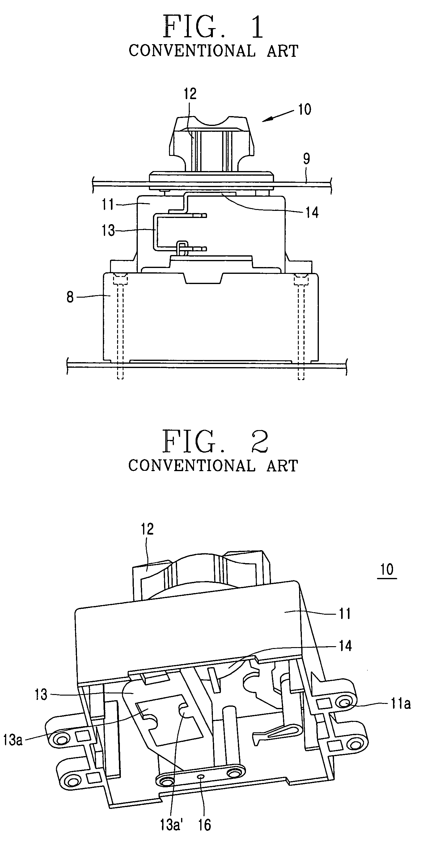
Accordingly, because of the two different rotational centers, it is difficult to control a stroke required for the operation of the handle of the mold cased circuit breaker 8 and an operational range of the external operating handle 12 according to the stroke.
In particular, upon operating a reset function for which a large amount of power is required, an unreasonable force is applied to the handle lever 13 or resin components of other switching mechanisms.
As a result, deformation or damage may occur on the handle lever 13 or the switching mechanisms, and thus the reset operation may not be successfully done or may be performed faultily.

Method used


Image

  • External operating handle mechanism for mold cased circuit breaker
  • External operating handle mechanism for mold cased circuit breaker
  • External operating handle mechanism for mold cased circuit breaker

Examples


Embodiment Construction

[0035]Reference will now be made in detail to the preferred embodiments of the present invention, examples of which are illustrated in the accompanying drawings.

[0036]Hereinafter, an external operating handle mechanism for a mold cased circuit breaker in accordance with an embodiment of the present invention will now be explained in detail with reference to the attached drawings.

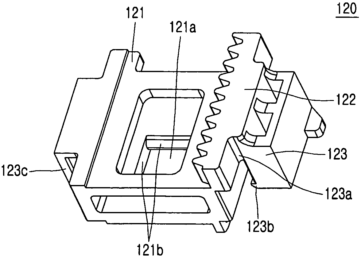
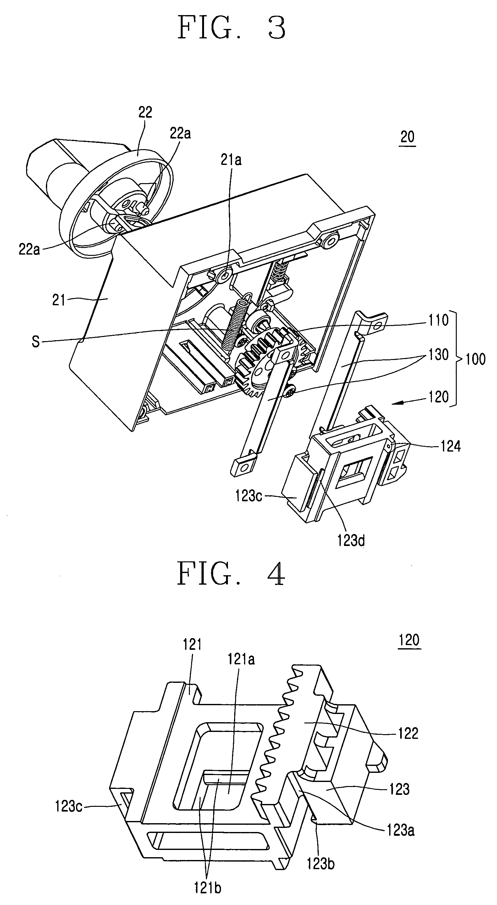
[0037]Referring to FIG. 3, an external operating handle mechanism 20 for a mold cased circuit breaker in accordance with an embodiment of the present invention may include: an external operating handle 22; a pinion gear 110 coupled to the external operating handle 22 to thus rotate in response to a rotation of the external operating handle 22; a movable member 120 having a rack gear portion coupled to the pinion gear to linearly move according to the rotation of the pinion gear, and having a handle connecting portion connected to a handle 15 (refer to FIG. 5) of the mold cased circuit breaker 8 (refer to FIG...


PUM


Abstract

An external operating handle mechanism for a mold cased circuit breaker comprising: an external operating handle; a pinion gear coupled to the external operating handle to be rotatable in response to a rotation of the external operating handle; a movable member provided with a rack gear portion coupled to the pinion gear to be linearly movable according to the rotation of the pinion gear, and provided with a handle connecting portion connected to the handle of the mold cased circuit breaker to linearly move the handle of the mold cased circuit breaker; and a guide member for guiding the movable member to linearly move, by which it is easy to control a stroke required for a displacement of the handle of the mold cased circuit breaker and the displacement of the external operating handle according to the stroke, and it is possible to accurately and efficiently transfer power upon performing a reset operation. Accordingly, unreasonable force may not be applied to resin molding components related to the reset operation including a handle among switching mechanisms, and thus damage or deformation of these components and a unsuccessful or imperfect reset operation can be prevented.

Description

BACKGROUND OF THE INVENTION[0001]1. Field of the Invention[0002]The present invention relates to a Mold Cased Circuit Breaker (so called abbreviated as MCCB), and more particularly, to an external operating handle mechanism for a mold cased circuit breaker for operating an handle of the mold cased circuit breaker within a power distributing board or confirming an on / off state or a tripped state of the mold cased circuit breaker on a front panel of the power distributing board having the mold cased circuit breaker therein.[0003]2. Background of the Prior Art[0004]In general, a mold cased circuit breaker is a type of an electric apparatus using a relatively low voltage for protecting a circuit or a load by automatically breaking the circuit upon electrically occurring an overload or a short circuit. The mold cased circuit breaker typically has a case formed by molding a resin having electrical insulating properties, and thus is referred to as the Mold Cased Circuit Breaker (MCCB). A p...

Claims


Application Information

Patent Timeline
Patent Type & Authority Patents(United States)
IPC IPC(8): H01H3/20
CPCH01H3/08H01H3/40H01H2071/565H01H71/10
Inventor SUH, JEONG-WOO
Owner LG IND SYST CO LTD
Learn More