Apparatus and method for extracting a maximum pulse width of a pulse width limiter

a limiter and maximum pulse technology, applied in pulse generators, pulse manipulation, pulse techniques, etc., can solve the problems of limiting the resolution of this technique, affecting the reliability of the signal at such frequencies, and affecting the reliability of the signal, so as to reduce the amount of chip area used.

Inactive Publication Date: 2008-04-15
GOOGLE LLC
View PDF34 Cites 6 Cited by
  • Summary
  • Abstract
  • Description
  • Claims
  • Application Information

AI Technical Summary

Benefits of technology

[0010]The illustrative embodiments described herein provide an apparatus and method for extracting the maximum pulse width of a pulse width limiter. The apparatus and method of the illustrative embodiments performs such extraction using a circuit that is configured to eliminate the majority of the delay cells utilized in the circuit arrangement described in commonly assigned and co-pending U.S. patent application Ser. No. 11 / 109,090 (hereafter referred to as the '090 application). The elimination of these delay cells is made possible in one illustrative embodiment by replacing an OR gate in the circuit configuration of the '090 application with an edge triggered re-settable latch. The replacement of the OR gate with the edge triggered re-settable latch reduces the amount of chip area used in addition to the power consumption of the circuit.

Problems solved by technology

If the pulse width is too wide, for example, it can cause pre-charged array nodes to lose their logic value and result in array failure.
However, typical laboratory equipment that can guarantee signal integrity at such frequencies is often cost-prohibitive.
However, this approach relies on the discrete phases available from the VCO and, therefore, the discreteness limits the resolution of this technique.
Moreover, unless the VCO is locked by, for example, a phase-locked loop (PLL), the VCO input can be compromise by large jitter at each of its phases, thereby increasing the measurement uncertainty.
This approach, however, is also subject to limitations.
Thus, while one can employ the pulse stretchers to bring the test output within the bandwidth requirement of the off-chip laboratory measurement equipment, the desired measurement remains unknown without an often complicated additional characterization of the pulse stretchers themselves.
The delay cells required for providing this fixed amount of delay consume a large chip area and may also consume a large amount of power.

Method used


Image

  • Apparatus and method for extracting a maximum pulse width of a pulse width limiter
  • Apparatus and method for extracting a maximum pulse width of a pulse width limiter
  • Apparatus and method for extracting a maximum pulse width of a pulse width limiter

Examples


Embodiment Construction

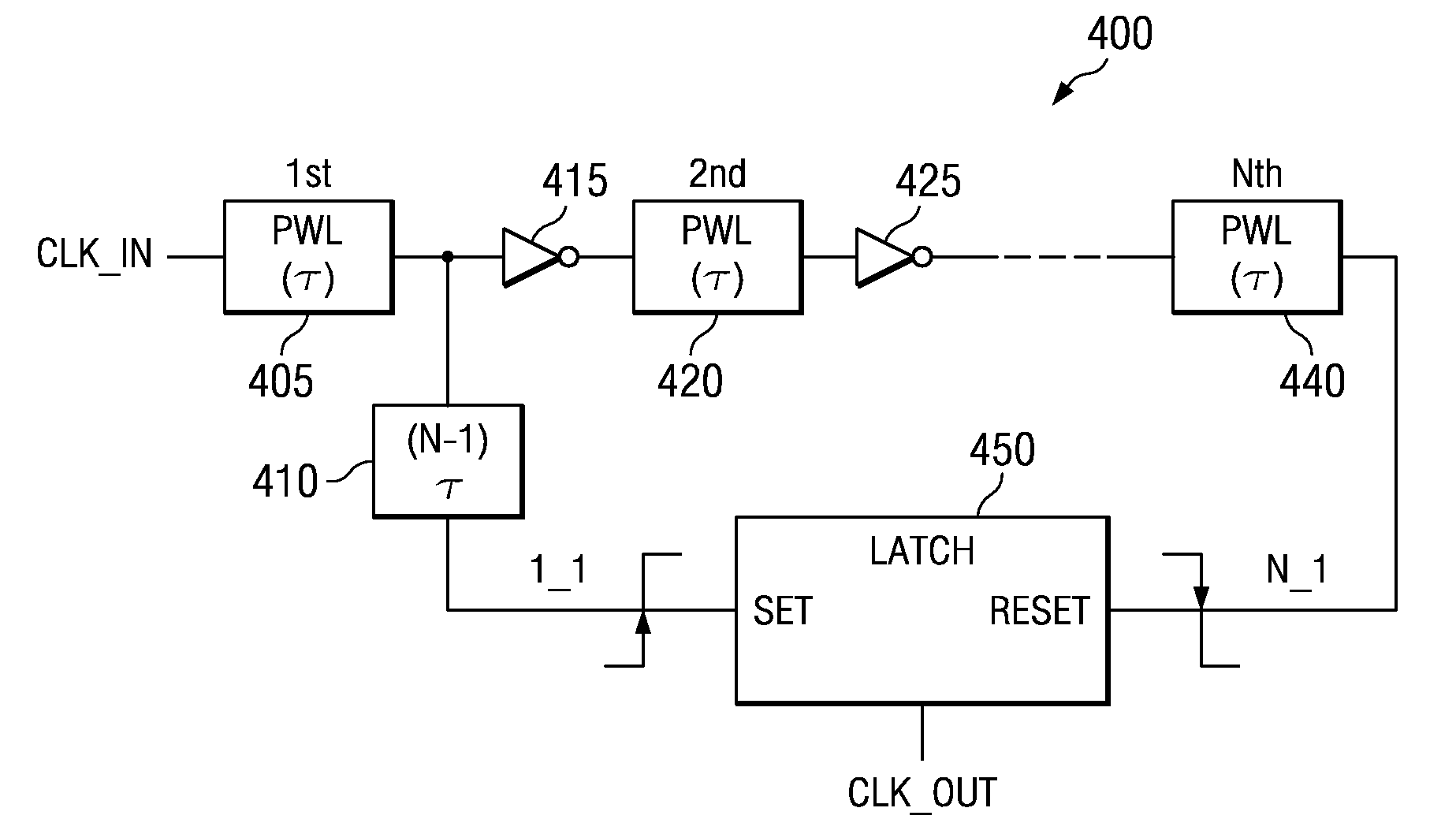
[0031]The mechanisms of the illustrative embodiments make improvements over the mechanisms of the illustrative embodiments in U.S. patent application Ser. No. 11 / 109,090 (hereafter referred to as the '090 application). Thus, in order to best understand the improvements provided by the illustrative embodiments, it is first beneficial to provide a description of the mechanisms of the illustrative embodiments set forth in the '090 application. FIGS. 1-3 hereafter provide illustrative examples of the mechanisms described in the '090 application.

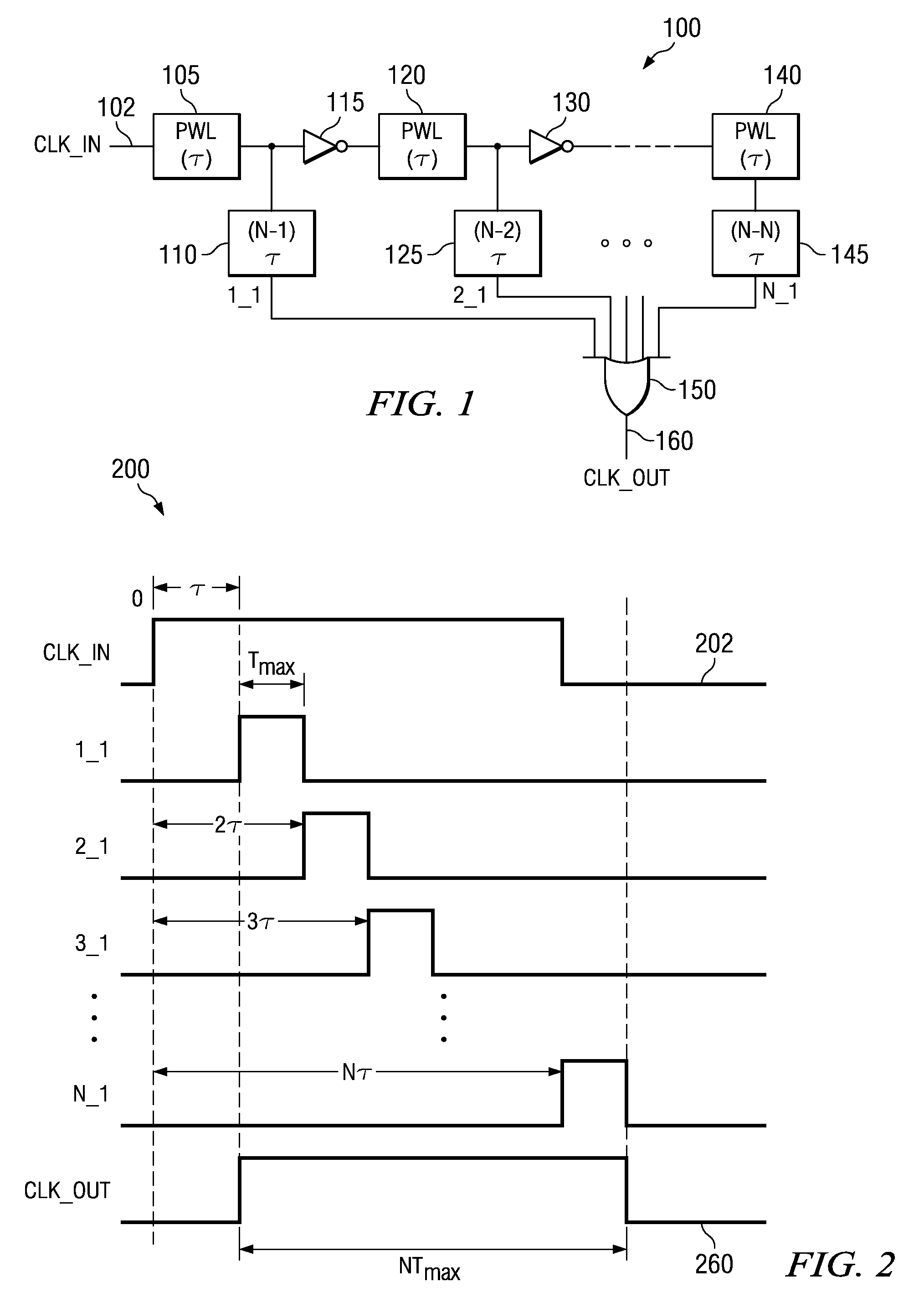
[0032]FIG. 1 is an exemplary block diagram depicting a pulse-width limiter output characterization system 100 in accordance with the illustrative embodiments described in the '090 application. As shown in FIG. 1, the pulse-width limiter output characterization system 100 includes a pulse-width limiter (PWL) 105 which is one or more circuits, or other suitable logic, that is configured to perform pulse-width limiting operations. In one illustrativ...


PUM


Abstract

An apparatus and method for extracting a maximum pulse width of a pulse width limiter are provided. The apparatus and method of the illustrative embodiments performs such extraction using a circuit that is configured to eliminate the majority of the delay cells utilized in the circuit arrangement described in commonly assigned and co-pending U.S. patent application Ser. No. 11 / 109,090 (hereafter referred to as the '090 application). The elimination of these delay cells is made possible in one illustrative embodiment by replacing an OR gate in the circuit configuration of the '090 application with an edge triggered re-settable latch. The replacement of the OR gate with the edge triggered re-settable latch reduces the amount of chip area used in addition to the power consumption of the circuit.

Description

BACKGROUND[0001]1. Technical Field[0002]The present application relates generally to the field of circuit design and testing. More specifically, the present application is directed to an apparatus and method for extracting a maximum pulse width of a pulse width limiter.[0003]2. Description of Related Art[0004]In many modern computer applications, especially those dealing with large arrays, the maximum pulse width of clock signals operating on these arrays needs to be limited. If the pulse width is too wide, for example, it can cause pre-charged array nodes to lose their logic value and result in array failure. Thus, it is common for a clock source to be pulse-width limited before being asserted onto array grids. One example of a technique for limiting the maximum pulse width of a clock source is described in commonly assigned and co-pending U.S. Patent Application Publication No. 2005 / 0091620 entitled “A Simplified Method for Limiting Clock Pulse Width,” filed on Oct. 23, 2003.[0005...

Claims


Application Information

Patent Timeline
Patent Type & Authority Patents(United States)
IPC IPC(8): H03K3/017
CPCH03K5/1534H03K5/156H03K2005/00293
Inventor BOERSTLER, DAVID W.HAILU, ESKINDERQI, JIEMING
Owner GOOGLE LLC
Why Eureka
Try Eureka