
System and method for time-delay integration imaging

a technology of time delay and imaging, applied in the field of system and method of time delay integration (tdi) imaging, to achieve the effects of reducing image smear impact, reducing data latency, and increasing update ra

Active Publication Date: 2008-04-15
THE BF GOODRICH CO
View PDF9 Cites 13 Cited by
  • Summary
  • Abstract
  • Description
  • Claims
  • Application Information

AI Technical Summary

Benefits of technology

The present invention provides an improved system and method for time-delay integration (TDI) imaging of objects. The system includes an optical arrangement, an assembly of multiple detectors, and a signal processor. The detectors are arranged in a vertical scanning direction corresponding to the direction of movement of the scene, and are separately capable of producing an image of the object for each transit period in accordance with a time-delay integration technique. The system can further include a drive element capable of selectively clocking the detectors based upon the detectors producing an image of the object. The detectors can be arranged in a number of manners to provide advantages during operation of the system, such as determining the angular position of the object based upon the remaining image(s) independent of corrupt images, introducing diversity in fixed pattern errors, and introducing diversity in s-curve errors. The technical effects of the invention include higher update rate, reduced data latency, robustness in space radiation environments, reduced impact of image smear, reduced impact of correlated fixed pattern errors, reduced power required to perform detector clocking, and reduced impact of degraded charge transfer efficiency.

Problems solved by technology

More particularly, the detectors of the assembly can be arranged such that, when the error introduced in the system comprises a fixed pattern error, the fixed pattern error is uncorrelated from detector to detector to thereby introduce diversity in the fixed pattern error over the assembly.

Method used


Image

  • System and method for time-delay integration imaging
  • System and method for time-delay integration imaging
  • System and method for time-delay integration imaging

Examples


Embodiment Construction

[0021]The present invention now will be described more fully hereinafter with reference to the accompanying drawings, in which exemplary embodiments of the invention are shown. This invention may, however, be embodied in many different forms and should not be construed as limited to the embodiments set forth herein; rather, these embodiments are provided so that this disclosure will be thorough and complete, and will fully convey the scope of the invention to those skilled in the art. Like numbers refer to like elements throughout.

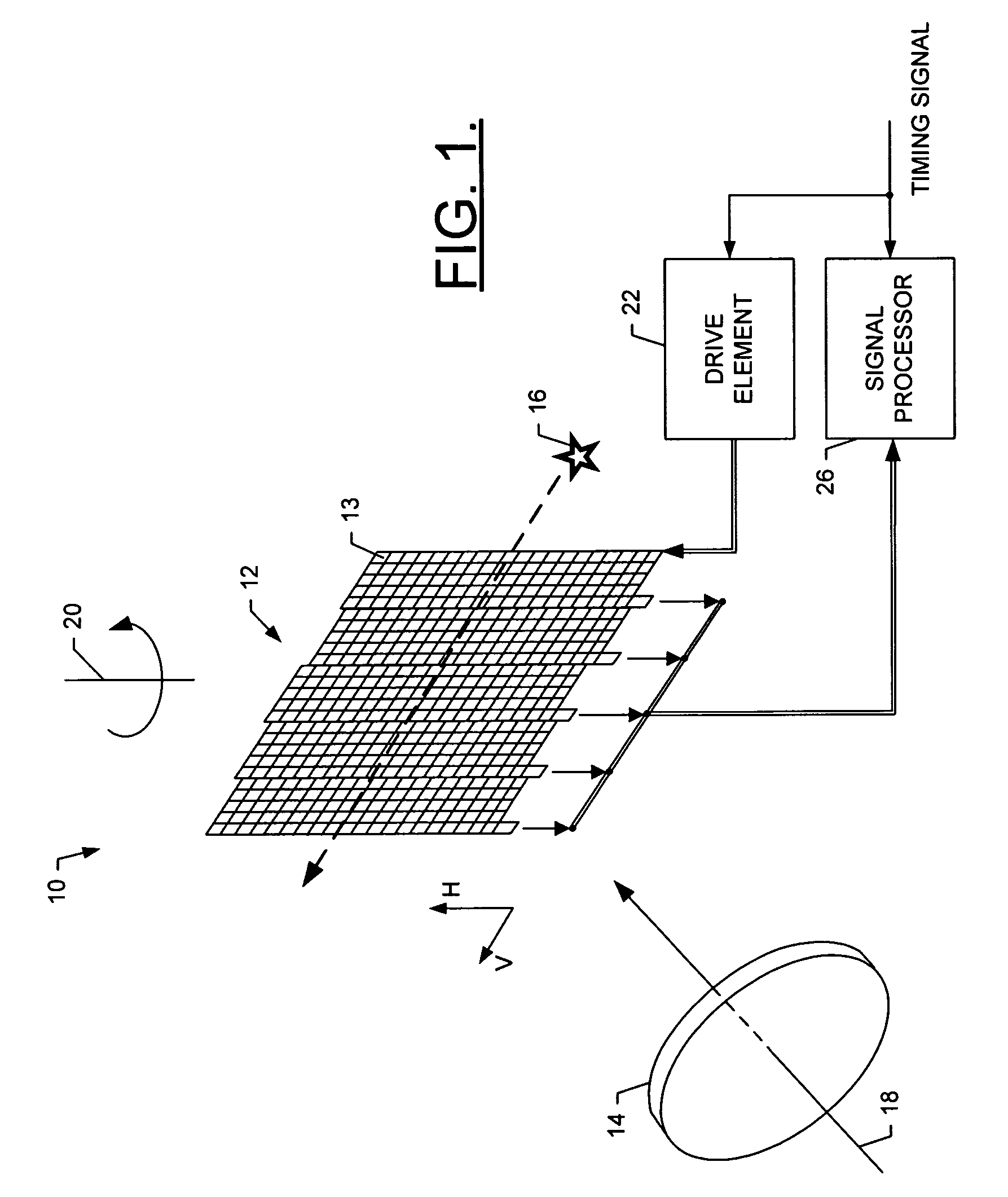
[0022]Referring to FIG. 1, an illustration of one type of system that would benefit from exemplary embodiments of the present invention is provided. The system and method of exemplary embodiments of the present invention will be primarily described in conjunction with star scanning in spacecraft attitude control applications. It should be understood, however, that the system and method of exemplary embodiments of the present invention can be utilized in co...


PUM


Abstract

A system is provided that includes an optical arrangement, an assembly of a plurality of detectors, and a signal processor. The optical arrangement is capable of viewing a scene that includes an object, where the scene is capable of moving through a field of view of the optical arrangement during each of a plurality of transit periods. The detectors of the assembly are arranged in a vertical scanning direction corresponding to a direction of movement of the scene, and are separately capable of producing an image of the object for each transit period in accordance with a time-delay integration technique. The signal processor, then, is capable of determining the angular position of the object for each transit period based upon the images produced by the detectors.

Description

FIELD OF THE INVENTION[0001]The present invention generally relates to systems and methods for time-delay integration (TDI) imaging and, more particularly, to systems and methods for TDI imaging of astronomical objects (e.g., stars) observed from a spacecraft to thereby determine and control the attitude of the spacecraft.BACKGROUND OF THE INVENTION[0002]In the space industry, spacecraft such as satellites are positioned in space for a number of different purposes including, for example, collecting and / or communicating data, information and the like. To effectively operate, however, the attitude of these satellites, including the satellites' azimuth and elevation angle, must typically be stabilized. One method to stabilize the attitude of a satellite is to set it in a spinning motion. Being in an otherwise uncontrolled environment, however, a number of different objects and / or events can disrupt a satellite's attitude, and accordingly, disrupt proper operation of the satellite. To d...

Claims


Application Information

Patent Timeline
Patent Type & Authority Patents(United States)
IPC IPC(8): G01C21/02G01B11/26G01C21/00H04B7/185
CPCH04N5/262G11C19/282
Inventor FLYNN, DAVID JOHN
Owner THE BF GOODRICH CO
Learn More