
Ball-and-socket joint

a ball-and-socket joint technology, applied in the direction of pivots, shafts and bearings, couplings, etc., can solve the problems of premature wear of joints, and achieve the effect of reducing the requirements of dimensional tolerances affecting the service li

Inactive Publication Date: 2008-04-15
ZF LEMFOERDER METALLWAREN AG
View PDF32 Cites 25 Cited by
  • Summary
  • Abstract
  • Description
  • Claims
  • Application Information

AI Technical Summary

Benefits of technology

[0003]The object of the present invention is therefore to improve a ball-and-socket joint of this type such that the high requirements in terms of dimensional tolerances which affect the service life can be reduced during the manufacture of the ball-and-socket joint.
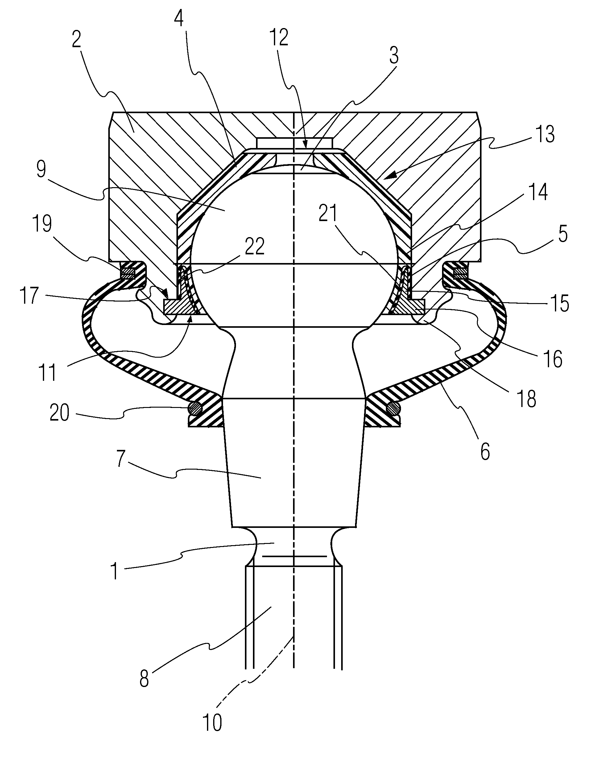
[0004]According to the invention, a ball-and-socket joint is provided with a pivot pin accommodated rotatably and tiltably with a spherical joint area in a bearing shell. The bearing shell is in turn arranged in a recess of a joint housing. A closing ring fixes the bearing shell in the joint housing in the axial longitudinal direction of the pivot pin by at least one surface pair. An intermediate element made of an elastic material (elastic element) is arranged between the corresponding contact surfaces on the bearing shell and the closing ring. The intercalation of the elastic element permits within certain limits an oblique position of the contact surfaces for fixing the bearing shell, so that the function of the ball-and-socket joint is essentially preserved both in the new state and after a wear situation resulting from the advanced duration of use, because tilting between the bearing shell and the closing ring is prevented from occurring. Increased tolerances as a consequence of advanced wear can be avoided by a defined pretension of the intermediate element.
[0005]In addition, axial tolerances can also be compensated within certain limits. A reduction of the manufacturing costs of the individual components of the ball-and-socket joint and consequently an overall cost advantage are achieved due to the design according to the present invention without adverse effects on the desired long service life having to be feared.

Problems solved by technology

The mounting is usually performed by a rolling operation, as a result of which a one-sided contact of the bearing shell with the closing ring may develop, which leads to premature wear of the joint and as a consequence of this to an excessive clearance in the joint.

Method used


Image

  • Ball-and-socket joint
  • Ball-and-socket joint
  • Ball-and-socket joint

Examples


Embodiment Construction

[0017]Referring to the drawings in particular, FIG. 1 shows a ball-and-socket joint, which comprises essentially a pivot pin 1, a joint housing 2, a one-part or multipart bearing shell 4 arranged within a recess 3 of the joint housing 2, a closing ring 5 as well as a sealing bellows 6 consisting of an elastic material. Such a ball-and-socket joint may be used, e.g., in motor vehicles and specifically in the chassis or on steering mechanism parts of passenger cars and utility vehicles. It is used to make possible a controlled rotary and tilting movement between two components, wherein the pivot pin with its free end projecting from the joint housing, which has a cone 7 and a threaded fastening end 8 joining the cone is fixed at a motor vehicle component. The other, movable component corresponding to this is fixed to the joint housing 2 with fastening means not specifically shown here. At the end located opposite the fastening end 8, the pivot pin 1 has a spherical joint area 9, which...


PUM


Abstract

A ball-and-socket joint has a pivot pin accommodated rotatably and tiltably with a spherical joint area in a bearing shell. The bearing shell is in turn arranged in the recess of a joint housing. A closing ring fixes the bearing shell in the joint housing in the axial longitudinal direction of the pivot pin by at least one surface pair. Corresponding to a first solution variant, an intermediate element made of an elastic material may be arranged between the corresponding contact surfaces of the surface pair on the bearing shell and the closing ring. As an alternative an insert element may be arranged between the outer contour of the bearing shell and the bottom area of the recess, wherein at least one intermediate element made of an elastic material is arranged between the outer surface of the insert element and the corresponding inner surface of the recess. The requirement imposed on the dimensional accuracy of the ball-and-socket joint components can be substantially reduced due to these solution variants, which contributes to a reduction of the manufacturing costs.

Description

FIELD OF THE INVENTION[0001]The present invention pertains to a ball-and-socket joint with a pivot pin, which is accommodated rotatably and tiltably with a spherical joint area in a bearing shell, which is in turn arranged in the recess of a joint housing, wherein a closing ring fixes the bearing shell in the joint housing in the axial longitudinal direction of the pivot pin by at least one contact surface.BACKGROUND OF THE INVENTION[0002]Various different designs of ball-and-socket joints of the type described in the introduction have been known from the state of the art, and they are used, in particular, in vehicles and steering mechanisms of passenger cars and utility vehicles. A decisive criterion for the quality of the ball-and-socket joints used is their service life, which should be sufficiently long under difficult stress conditions. An essential requirement for ensuring a sufficient service life is the narrowest possible tolerances of the ball-and-socket joint components, a...

Claims


Application Information

Patent Timeline
Patent Type & Authority Patents(United States)
IPC IPC(8): F16C11/00F16C11/06F16C11/08
CPCF16C11/0614F16C11/0638F16C11/0671F16C11/069F16C11/086Y10T403/32631Y10T403/32713Y10T403/32721Y10T403/32737F16C11/06
Inventor BROKER, KLAUSNOE, HELMUT
Owner ZF LEMFOERDER METALLWAREN AG
Learn More