
High density data recording/reproduction method utilizing electron emission and phase change media, and data recording system adopting the same, and media for the system

a data recording and phase change technology, applied in nanoinformatics, instruments, record information storage, etc., can solve the problems of loss or detonation of data, limited data recording density of laser used for recording and reproducing data, and limited data recording density

Inactive Publication Date: 2008-04-08
SAMSUNG ELECTRONICS CO LTD
View PDF25 Cites 7 Cited by
  • Summary
  • Abstract
  • Description
  • Claims
  • Application Information

AI Technical Summary

Benefits of technology

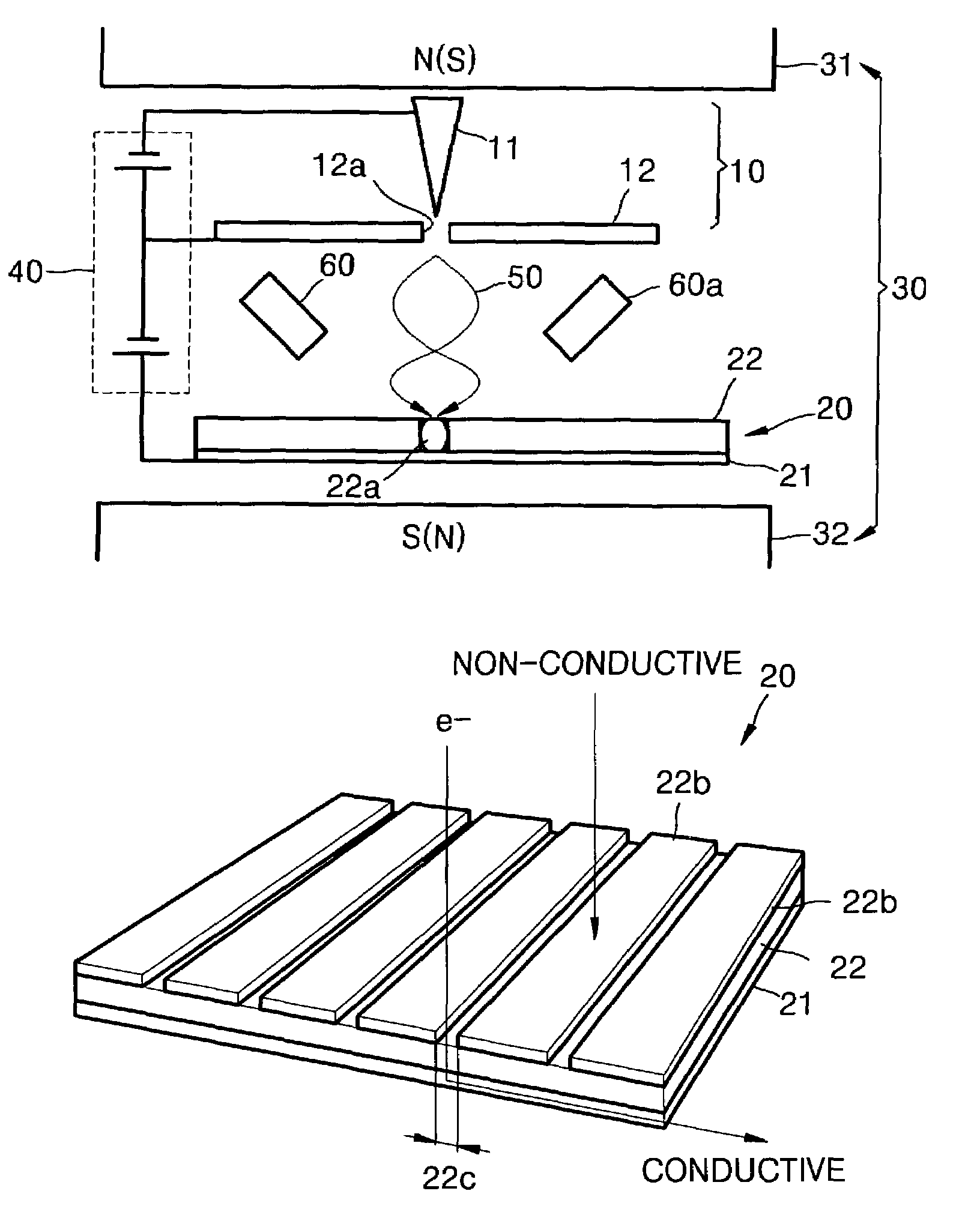
[0020]The data recording method and the data recording system adopting the same according to the present invention are able to store and erase data by remotely scanning an electron beam into media for high density data storage and data decryption, to detect scattering of the electron beam from media by scanning the electron beam into stored data, or to detect current flowing through a data portion, thereby decrypting data.

Problems solved by technology

Compact discs (CDs) and digital versatile discs (DVDs), in which a laser is used for recording and reproducing data have limited data recording density due to limitations on a wavelength of the laser.
However, this recording density is also limited due to the size of a probe for approaching media and recording or reproducing data.
These methods, however, are slow and may cause loss or detonation of data due to abrasion and vibration of the tip.
However, these methods require very large scale facilities, and thus cannot be practically applied to a portable data recording system.

Method used


Image

  • High density data recording/reproduction method utilizing electron emission and phase change media, and data recording system adopting the same, and media for the system
  • High density data recording/reproduction method utilizing electron emission and phase change media, and data recording system adopting the same, and media for the system
  • High density data recording/reproduction method utilizing electron emission and phase change media, and data recording system adopting the same, and media for the system

Examples


Embodiment Construction

[0032]Korean Patent Application No. 2001-58854, filed on Sep. 22, 2001, and entitled: “High Density Data Recording / Reproduction Method Utilizing Electron Emission and Phase Change Media, and Data Recording System Adopting the Same, and Media for the System,” is incorporated by reference herein in its entirety.

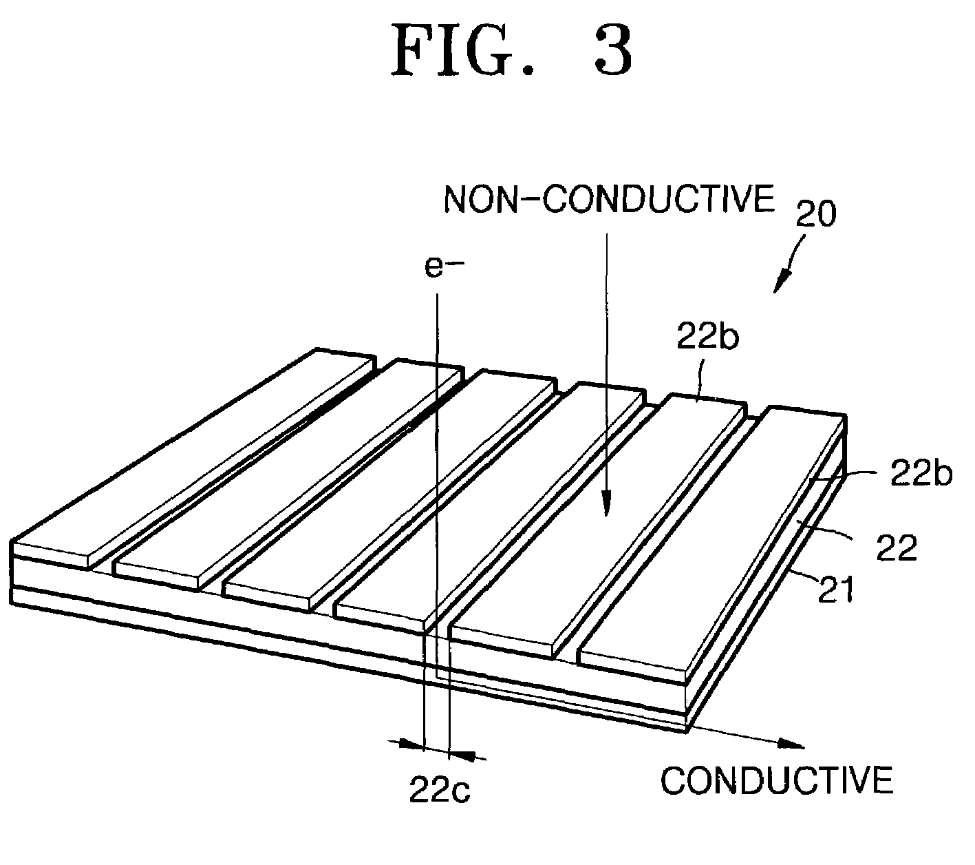
[0033]Referring to FIGS. 1 and 2, an electron generating source 10 including a gate electrode 12 and a micro-tip 11 is positioned above media 20 including a data recording layer 22 having a data recording region formed of a phase change material such as GeTeSb, and a substrate 21 for supporting the data recording layer 22. As shown in FIG. 2, the micro-tip 11 is held at the end of a conductive cantilever 11a, and a vertical magnetic field B is formed by a magnetic field generating source 30. Meanwhile, an upper magnetic field generating source 31 and a lower magnetic field generating source 32 constituting the magnetic field generating source 30 are respectively positioned abov...


PUM


Abstract

A rapid data recording / reproducing method, a data recording system adopting the same, media for the system, and a tracking method, wherein the recording / reproducing method includes preparing media having a data recording layer in which a phase change is generated through electron absorption, generating electrons using an electron generating source at a position separated from the data recording layer by a predetermined interval, forming a magnetic field on the path of the electrons and cyclotron moving the electrons, recording data through local melting and cooling due to absorption of the electrons by the data recording layer. A micro-tip does not contact the data recording layer during electron collisions therewith, hence no damage is caused by or to the micro-tip. The present invention allows the region where the electron beam reaches the data recording layer to be minimized thereby maximizing the data recording density.

Description

BACKGROUND OF THE INVENTION[0001]1. Field of the Invention[0002]The present invention relates to a data recording / reproduction method, a data recording system adopting the same, media for the data recording system, and a tracking method for the data recording system. More particularly, the present invention relates to a data recording / reproduction method in which an electron beam is scanned into a phase change media, a data recording system adopting the same, media for the data recording system, and a tracking method for the data recording system.[0003]2. Description of the Related Art[0004]Compact discs (CDs) and digital versatile discs (DVDs), in which a laser is used for recording and reproducing data have limited data recording density due to limitations on a wavelength of the laser. A data storage system that uses a vertical magnetic recording method has a comparatively high recording density. However, this recording density is also limited due to the size of a probe for approa...

Claims


Application Information

Patent Timeline
IPC IPC(8): G11B9/00G01Q80/00G11B9/10G11B9/12
CPCB82Y10/00G11B9/10G11B9/14G11B9/1409G11B9/1418G11B9/1463G11B11/115
Inventor YOO, IN-KYEONGCHOI, WON-BONGSHIN, HYUN-JUNG
Owner SAMSUNG ELECTRONICS CO LTD
Learn More