
Method of making a water treatment composite pressure vessel

a composite pressure vessel and water treatment technology, applied in the direction of vessel construction details, container discharge methods, mechanical equipment, etc., can solve the problems of heavy and subject to corrosion, and the problem of unable to manufacture suitable thermoset plastic tanks, and achieve the effect of reducing the cost of production and maintenan

Inactive Publication Date: 2008-04-08
ENPRESS
View PDF75 Cites 23 Cited by
  • Summary
  • Abstract
  • Description
  • Claims
  • Application Information

AI Technical Summary

Benefits of technology

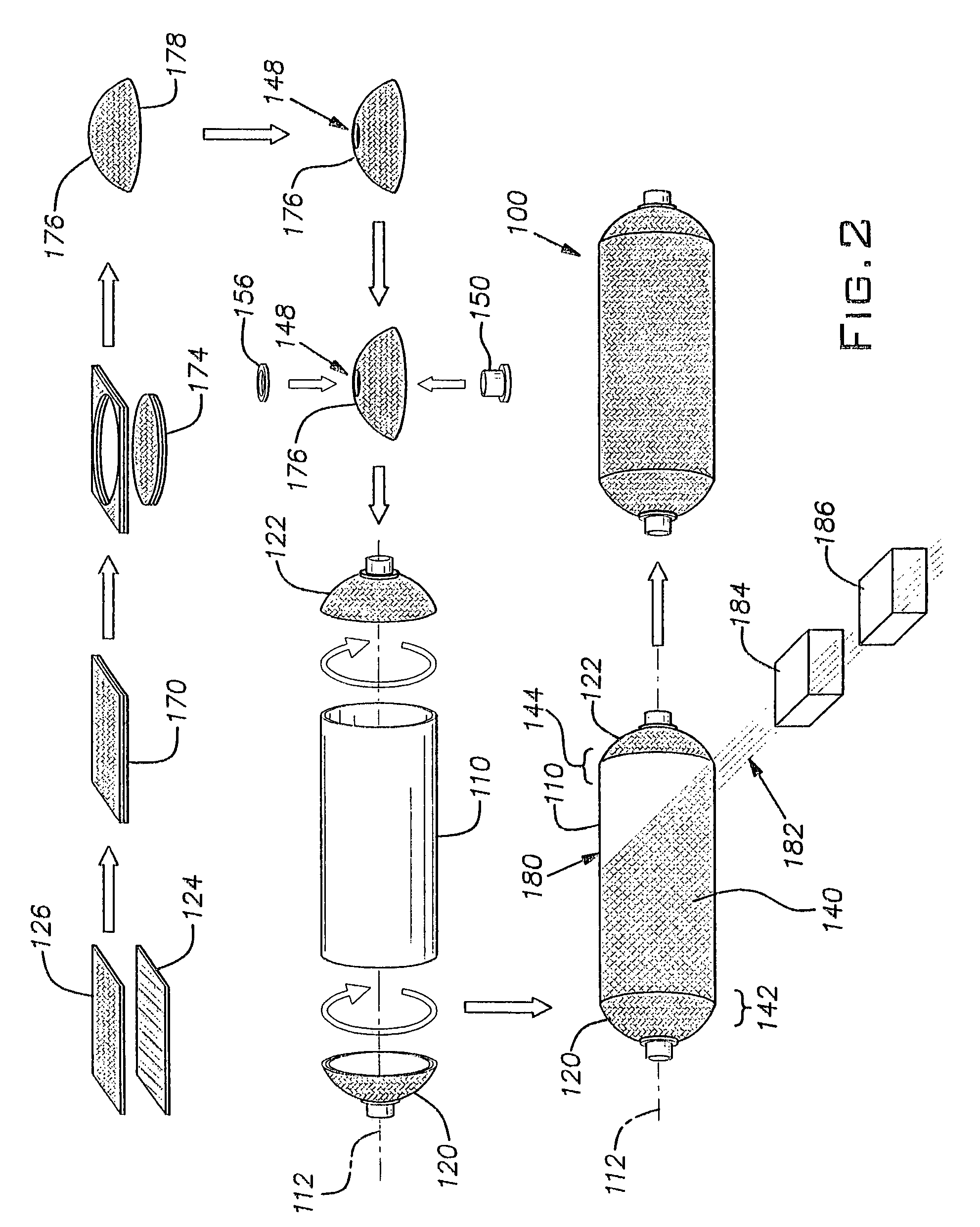
"The present invention provides a composite vessel with improved strength and durability. The vessel includes first and second endcaps and a liner, with the first layer being a thermoplastic layer and the second layer being a thermoplastic and glass fiber composite layer. The endcap has a dome-shaped body with a circular free end and an insert with a threaded inner surface and a radially projecting flange. The invention also provides a method for making a pressure vessel by molding thermoplastic and glass fibers into an endcap. Additionally, the invention provides a method and system for texturing the outer surface of a thermoplastic pressure vessel by using a pressurizable bladder with a desired texture formed on its inner surface. The method involves heating the outer vessel surface and inserting it into the bladder, which is then pressurized to conform the outer surface of the vessel to the texture of the bladder."

Problems solved by technology

Steel tanks are generally considered to be more durable than their plastic counterparts, but are heavier and subject to corrosion.
While the use of thermoset plastic has addressed the problem of corrosion associated with steel tanks, fabrication and manufacture of suitable thermoset plastic tanks has proven to be problematic.

Method used


Image

  • Method of making a water treatment composite pressure vessel
  • Method of making a water treatment composite pressure vessel
  • Method of making a water treatment composite pressure vessel

Examples


first embodiment

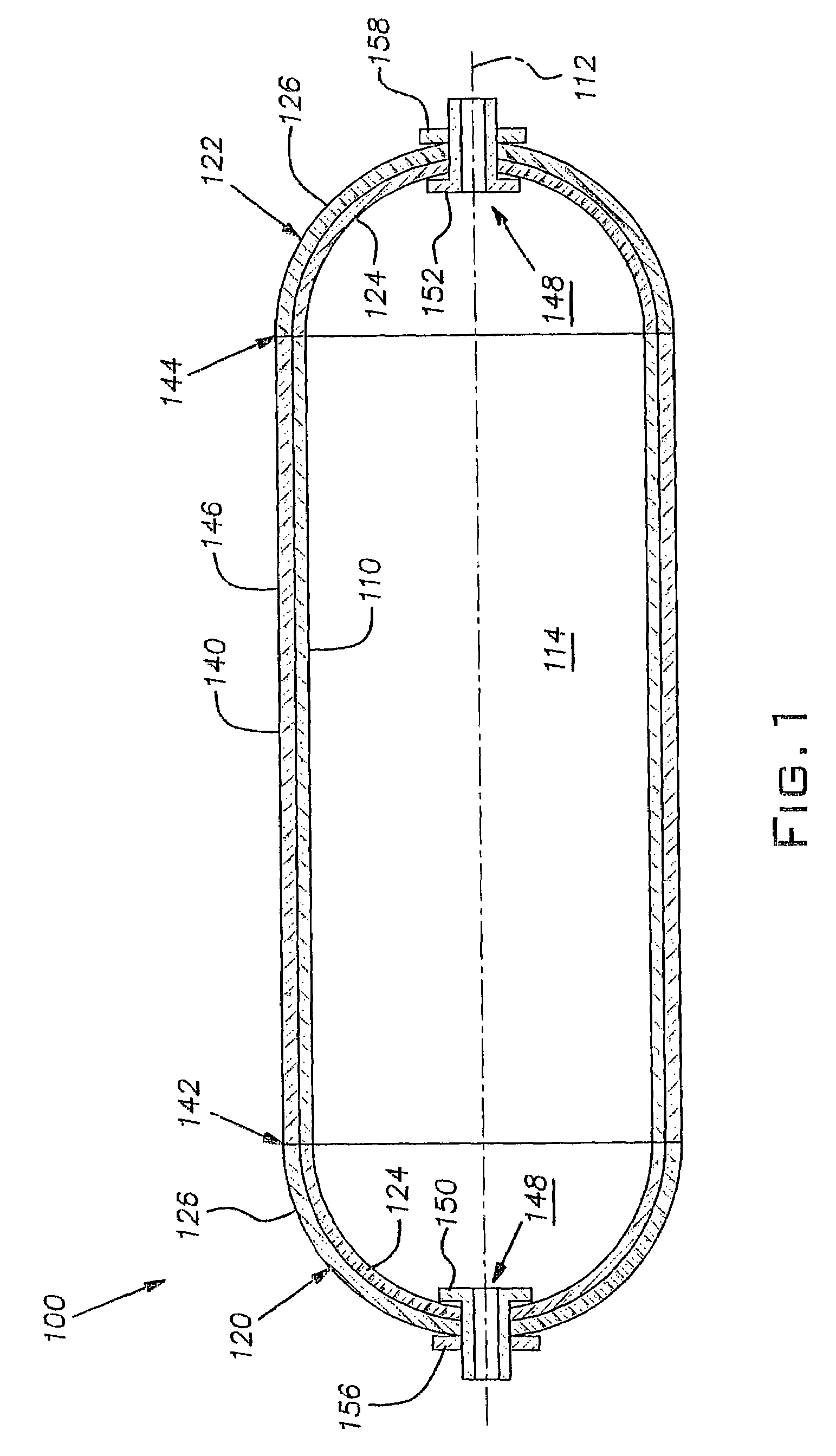
[0020]A composite pressure vessel 100 according to the present invention is shown in FIG. 1. The vessel 100 is a composite shell for use in, for example, a residential water system, a water storage tank, and a water treatment system.

[0021]The vessel 100 includes a non-fiber reinforced thermoplastic, polypropylene liner 110 that defines an axis 112. The liner 110 may be extruded, injection molded, or formed by other means.

[0022]The vessel 100 also includes first and second dome-shaped, semi-hemispherical endcaps 120, 122. The endcaps 120, 122 are generally identical and include a first, inner layer 124 and a second, outer layer 126. The first layer 124 is a thermoplastic polypropylene liner layer, while the second layer 126 is a reinforced thermoplastic, as will be described more fully hereinafter. In alternative embodiments, suitable endcaps are frusto-conical or flattened, and the endcaps need not be alike. Moreover, the endcaps may be of any desired shape or size.

[0023]The endcaps...

third embodiment

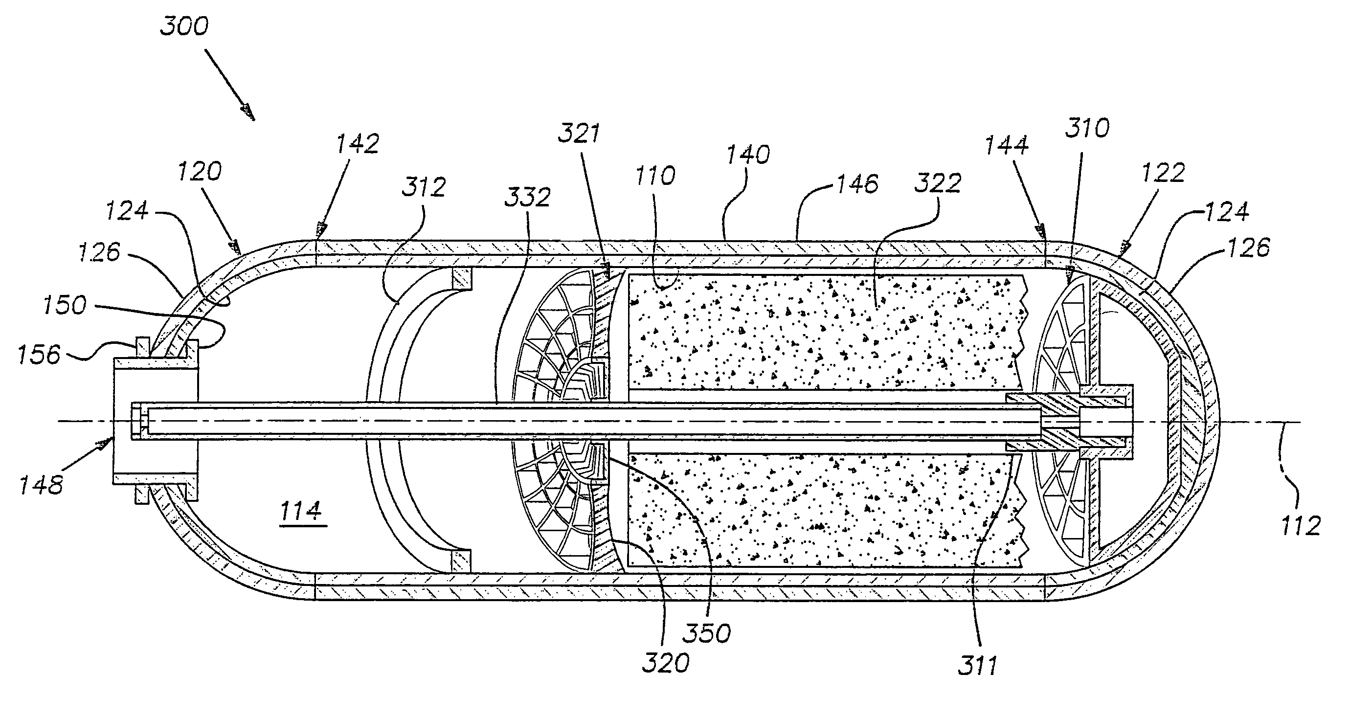
[0046]A vessel 300 comprising the invention is shown in FIG. 4. The vessel 300 includes many parts that are substantially the same as corresponding parts of the vessel 100; this is indicated by the use of the same reference numerals in FIGS. 1 and 4. The vessel 300 differs in that it includes a plurality of internal structures disposed within the cavity 114. The plurality of internal structures in the illustrated embodiment defines a water treatment assembly including a fluid diffuser 310, a reinforcing rib 312, a perforated separator 320, and filter media 322. The filter media 322 is, for example, activated carbon and is shown cut-away for clarity. Additional and optional filter media located opposite the separator 320 from the filter media 322 is not shown for clarity.

[0047]The ring-shaped separator 320, which is preferably formed from a thermoplastic material, defines a central aperture and a peripheral flange 321. Depending upon the size of the perforations or slotted openings f...


PUM

PropertyMeasurementUnit
lengthsaaaaaaaaaa
lengthsaaaaaaaaaa
areaaaaaaaaaaa

Abstract

A composite pressure vessel includes an endcap with first and second layers. The first layer is a thermoplastic layer and the second layer is a thermoplastic and glass fiber composite layer. A method for making the vessel includes placing commingled thermoplastic and glass fibers in a heated mold to melt the thermoplastic. The molten thermoplastic and the glass fibers are molded into the endcap shape. An outer surface of the pressure vessel is finished in accordance with another aspect of the invention. A pressurizable bladder with an inwardly facing surface is deflated. The outer surface of the vessel is heated to soften the thermoplastic. The pressure vessel is positioned in the bladder so that the inwardly facing surface of the bladder is adjacent to an outer surface of the pressure vessel. The bladder is pressurized to move the bladder inwardly into contact with the adjacent surfaces to each other.

Description

CROSS REFERENCE TO RELATED APPLICATIONS[0001]This application is a continuation of U.S. patent application Ser. No. 10 / 262,823, now abandoned filed Oct. 10, 2002, which claims priority to U.S. Provisional Application Ser. No. 60 / 329,134 filed Oct. 12, 2001.BACKGROUND OF THE INVENTION[0002]1. Field of the Invention[0003]The present invention relates generally to thermoplastic vessels and, more specifically, to composite thermoplastic pressure vessels and methods for making same.[0004]2. Discussion of Related Art[0005]Water tanks for use in commercial and household applications are typically made from steel or thermoset plastic. Steel tanks are generally considered to be more durable than their plastic counterparts, but are heavier and subject to corrosion.[0006]While the use of thermoset plastic has addressed the problem of corrosion associated with steel tanks, fabrication and manufacture of suitable thermoset plastic tanks has proven to be problematic. Factors including lengthy pro...

Claims


Application Information

Patent Timeline
Patent Type & Authority Patents(United States)
IPC IPC(8): B65H81/00B32B1/00F17C1/06F17C1/16F17C13/02
CPCF17C1/06F17C1/16F17C13/025F17C2203/0663F17C2203/067F17C2203/0673F17C2205/0305F17C2205/051F17C2209/2109F17C2209/2154F17C2209/221F17C2209/232F17C2209/234F17C2270/05F17C2201/0109F17C2201/054F17C2201/056F17C2203/0604F17C2203/0619F17C2203/0621F17C2203/066
Inventor CARTER, THOMAS G.PRISTAS, ROBERT J.
Owner ENPRESS
Learn More