Printer
a printing machine and printing plate technology, applied in the field of printing machines, can solve the problems of communication interface difficulties in handshake with host devices, and achieve the effect of enhancing power saving capability
- Summary
- Abstract
- Description
- Claims
- Application Information
AI Technical Summary
Benefits of technology
Problems solved by technology
Method used
Image
Examples
first embodiment
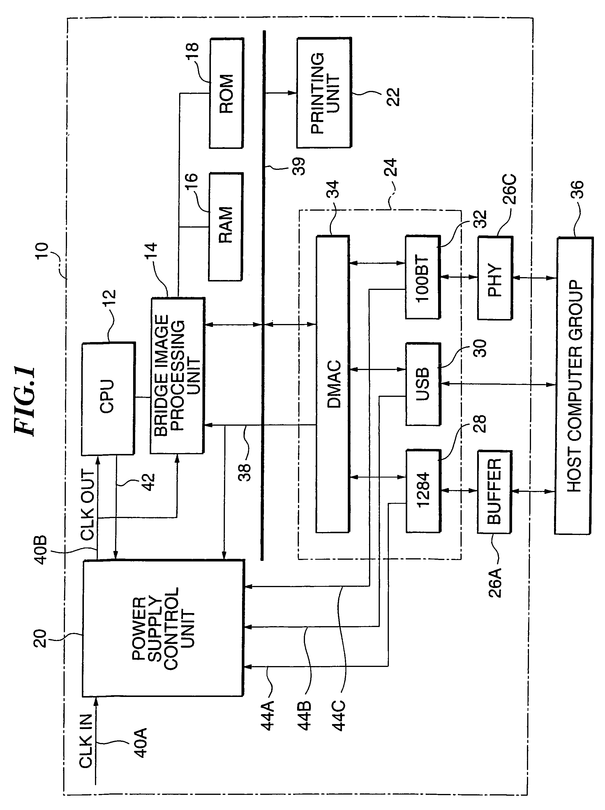
[0043]The first embodiment according to the invention will be described with reference to the accompanying drawings. FIG. 1 illustrates a schematic block diagram of a printer 10 to which the invention is applied.
[0044]As shown in FIG. 1, the printer 10 includes a CPU 12 as a control unit and judgment unit, a bridge image processing unit 14, a RAM 16, a ROM 18, a supply power control unit 20 as a setting unit, a character printing unit 22 as a print unit, a communication interface (I / F) 24 corresponding to various communication standards, a buffer 26A, and a physical layer I / F 26C.
[0045]The communication I / F 24 contains a 1284 interface 28 as the first communication interface that executes the communication control by the standard 1284 of IEEE (Institute of Electrical and Electronics Engineers), capable of a high speed parallel transfers a USB interface 30 as the first communication interface that executes the communication control by the USB (Universal Serial Bus), capable of a high...
second embodiment
[0091]Next, the second embodiment according to the invention will be described. In the second embodiment, a printer capable of a more effective control of the power consumption will be discussed.
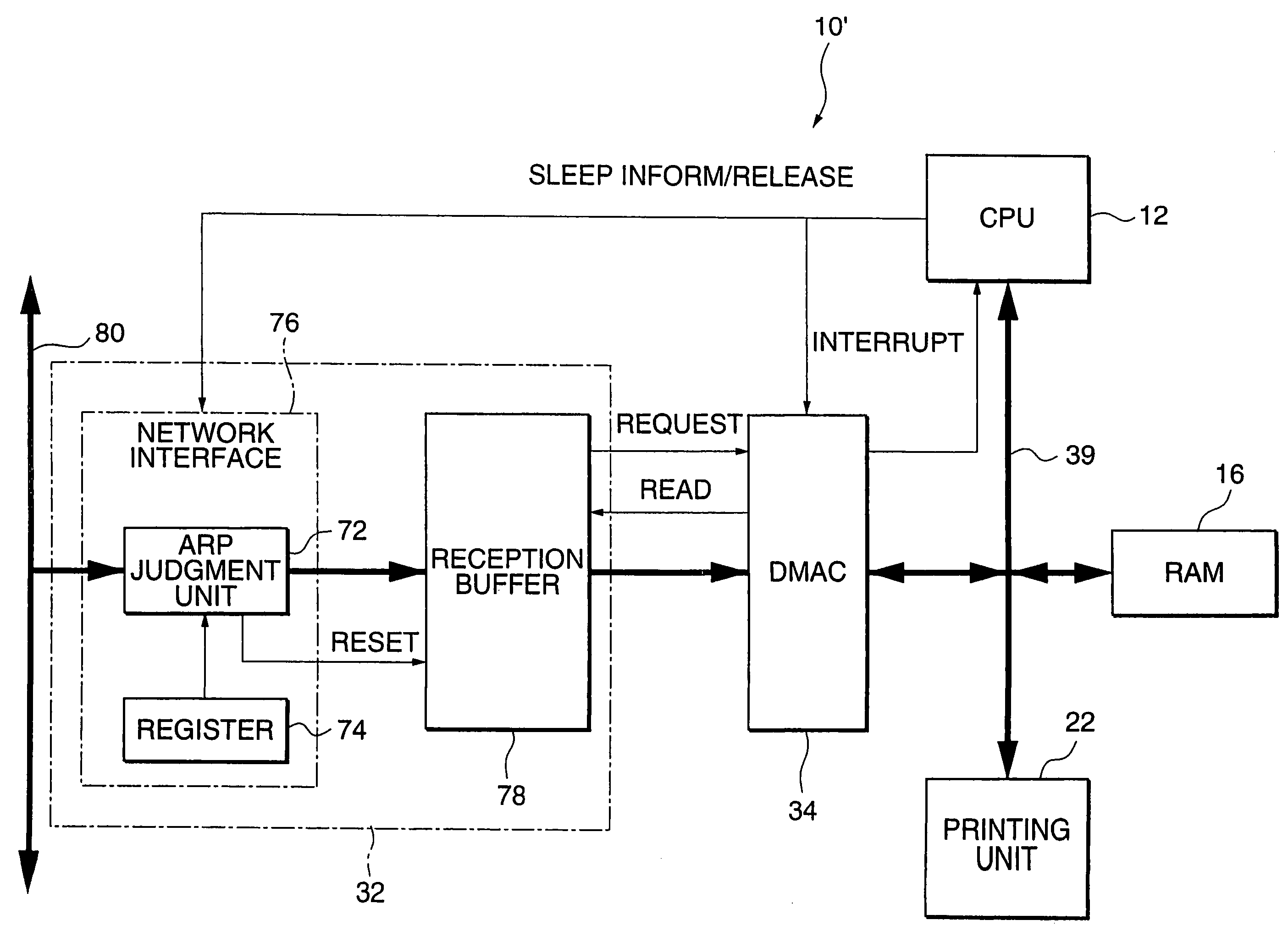
[0092]FIG. 8 illustrates a printer 10′ relating to the second embodiment, and takes up the characteristic parts of the printer 10′. And, the same parts as those of the printer 10 in FIG. 1 are given the same symbols, and the detailed explanations thereof will be omitted.
[0093]The 100BT interface 32 of the printer 10′ shown in FIG. 8 includes a network interface 76 containing an ARP judgment unit 72 and a register 74, and a reception buffer 78. In FIG. 8, the thick lines indicate the flows of reception data, and the thin lines indicate the flows of signals such as control signals except for the reception data.
[0094]The ARP judgment unit 72 corresponds to the judgment unit and the power consumption control unit of the invention according to one aspect of the invention, and the reception buffer...
third embodiment
[0114]Next, the third embodiment will be described. FIG. 13 illustrates a schematic block diagram of a printer relating to the third embodiment, in which the same symbols are given to the same parts as the printer 10 in FIG. 1, and the detailed explanations thereof will be omitted.
[0115]The communication I / F 24 of the printer 10″ shown in FIG. 13 includes a serial / parallel I / F 84, a control / print data analysis unit 86, a data request control unit 88, a power consumption control unit 90, a print data memory 92, a data storage control unit 94, a command data register 96, and the DMAC 34. Further, the printer 10″ is connected to the host computer 36 by a serial bus 98 (for example, USB).
[0116]The serial / parallel I / F 84, while executing the handshake control with the host computer 36, converts the data from the host computer 36 from serial into parallel to output the result to the control / print data analysis unit 86, and converts the data from the control / print data analysis unit 86 fro...
PUM
 Abstract
Description
Claims
Application Information
 - R&D
- Intellectual Property
- Life Sciences
- Materials
- Tech Scout
- Unparalleled Data Quality
- Higher Quality Content
- 60% Fewer Hallucinations
Browse by: Latest US Patents, China's latest patents, Technical Efficacy Thesaurus, Application Domain, Technology Topic, Popular Technical Reports.
© 2025 PatSnap. All rights reserved.Legal|Privacy policy|Modern Slavery Act Transparency Statement|Sitemap|About US| Contact US: help@patsnap.com


