Variable stroke property engine

a stroke property and engine technology, applied in the direction of machines/engines, liquid fuel feeders, mechanical apparatus, etc., can solve the problems of increasing the number of component parts and manufacturing work, difficult to prevent the lubricating oil from dripping onto the links, and the contact between the lubricating oil and the moveable parts is more problematic, so as to prevent the increase of the resistance of the engine, the effect of increasing the number of component parts and the amount of manufacturing work

Inactive Publication Date: 2008-04-01
HONDA MOTOR CO LTD
View PDF5 Cites 5 Cited by
  • Summary
  • Abstract
  • Description
  • Claims
  • Application Information

AI Technical Summary

Benefits of technology

[0007]In view of such problems of the prior art, a primary object of the present invention is to provide a variable stroke property engine that can prevent an increase in the resistance to the engine owing to the contact between the variable stroke piston mechanism and lubricating oil without increasing the number of component parts and the amount of manufacturing work.
[0008]A second object of the present invention is to provide a variable stroke property engine that can prevent a lubricating oil return passage or a crankcase ventilating passage from interfering with the variable piston stroke mechanism.
[0010]According to the present invention, at least some of such objects can be accomplished by providing a variable stroke property engine comprising a variable piston stroke mechanism including a plurality of links, wherein: a baffle plate is provided between the links and an oil surface of lubricating oil received in an oil pan. Because the baffle plate prevents the lubricating oil from contacting the moveable parts such as links, the resistance to such moveable parts can be minimized.
[0011]The variable stroke property engine is typically provided with a control shaft extending parallel with the crankshaft and supported by a crankcase of the engine via at least a pair of holders for adjusting a position of one of the links, the baffle plate being formed by a connecting portion connecting the holders such as bearing caps with each other. Because the connecting portion connecting the control shaft holders with one another also serves as a baffle plate that prevents the lubricating oil from contacting the links and control shaft, an increase in the resistance due to the lubricating oil contacting the variable piston stroke mechanism can be avoided without providing a separate baffle plate or increasing the number of components or the amount of manufacturing work. Also, the connecting member increases the rigidity of the control shaft holders by connecting the control shaft holders with one another so that the support rigidity for the control shaft and third link can be increased. Preferably, the connecting portion is provided with a shape of curved plate having a convex surface facing an oil surface of lubricating oil received in an oil pan so that the disturbance owing to the splashing of the lubricating oil may be minimized.
[0013]The engine may further comprise a balancer shaft and a housing covering at least a lower side of the balancer shaft facing an oil surface of lubricating oil received in an oil pan, the baffle plate includes an edge opposing the housing at a close proximity. Thereby, the connecting portion connecting the control shaft holders with one another substantially entirely separates the controls shaft from the oil surface in cooperation with the balancer housing provided under the crankshaft, the resistance to the engine can be effectively reduced without increasing the number of component parts or the amount of manufacturing work. If the baffle plate further comprises an extension extending from a part adjacent to an end wall of the crankcase to a part adjacent to an opposing part of the balancer shaft housing, the connecting portion and balancer housing can even more completely cover the oil surface of the lubricating oil without increasing the number of component parts or the amount of manufacturing work.
[0014]According to a preferred embodiment of the present invention, a passage communicating the interior of a cylinder head with the interior of a crankcase is provided in a side wall of a cylinder block remote from the control shaft. Thereby, the blowby gas and return lubricating oil would not contact the variable stroke piston mechanism so that the blowby gas and return lubricating oil can smoothly flow and an increase in the resistance to the engine owing to the splashing of lubricating oil onto the variable stroke piston mechanism can be avoided. Thus, the present invention is effective in ensuring a smooth flow of blowby gas and return lubricating oil, and preventing the variable stroke piston mechanism from becoming a source of resistance to the engine. Alternatively, the passage communicating the interior of a cylinder head with the interior of a crankcase may be provided in a partition wall of a cylinder block separating adjacent cylinders from each other. In either case, the lubricating oil and blowby gas are prevented from contacting the links, and an increase in the resistance to the movement of the links can be prevented while the structures of the links and passage are prevented from becoming complex.

Problems solved by technology

Particularly in the case of a variable stroke property engine, because there are a large number of moving parts such as links that move about within the crankcase, the contact between the lubricating oil and such moveable parts is more problematic that that in more conventional fixed stroke engines in which the piston and crankshaft are connected to each other simply by a connecting rod (single link).
However, in the case of an engine incorporated with a variable stroke piston mechanism including a plurality of links, providing a special baffle plate for preventing the splashing of lubricating oil onto the variable stroke piston mechanism leads to an increase in the number of component parts and the amount of manufacturing work.
However, in a variable stroke property engine, because the variable piston stroke mechanism includes a large number of moving parts including a plurality of links, it is difficult to prevent the lubricating oil from dripping onto the links and thereby increasing the resistance to the movement or from obstructing the flow of the blowby gas.

Method used


Image

  • Variable stroke property engine
  • Variable stroke property engine
  • Variable stroke property engine

Examples


Embodiment Construction

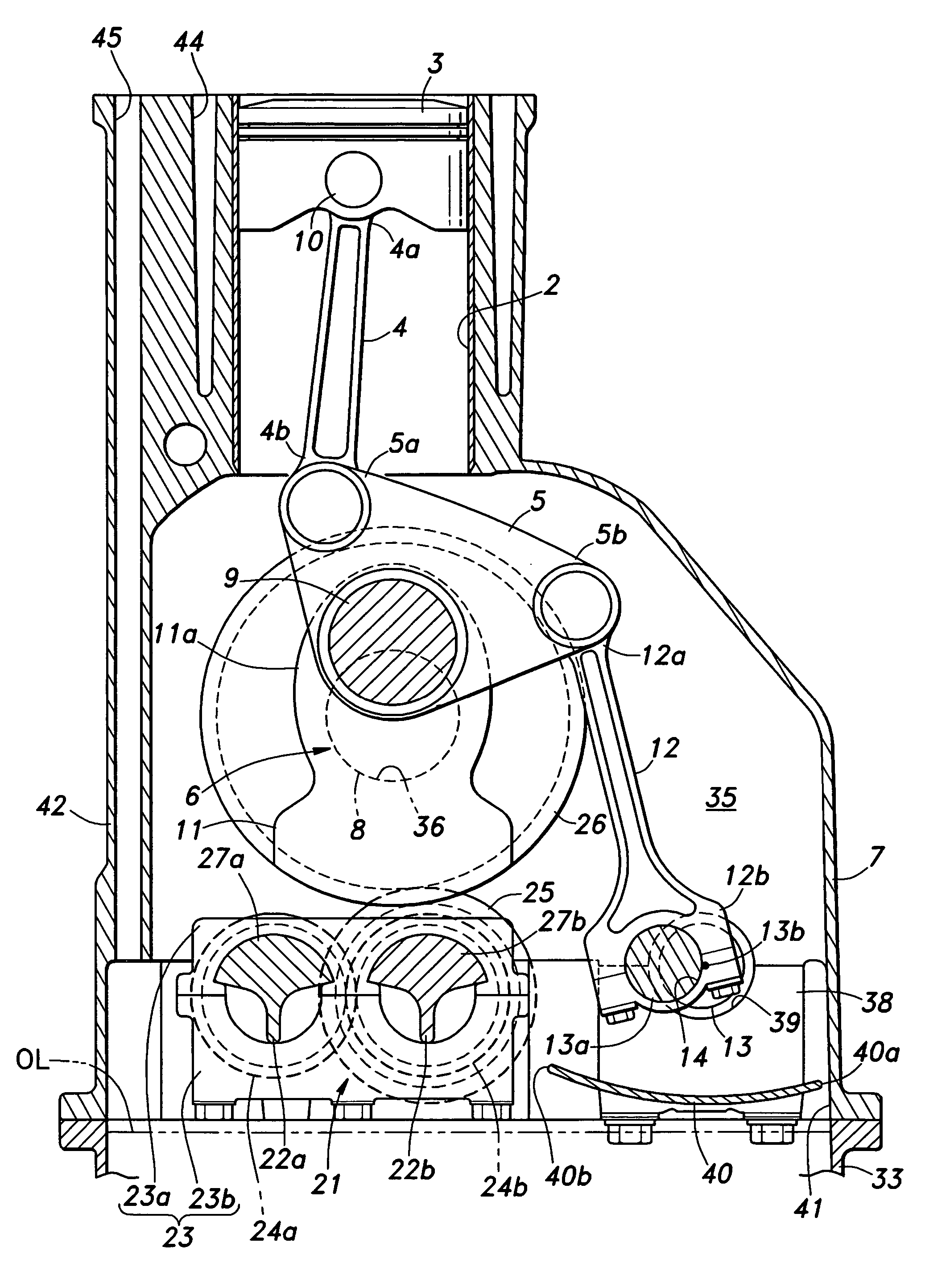
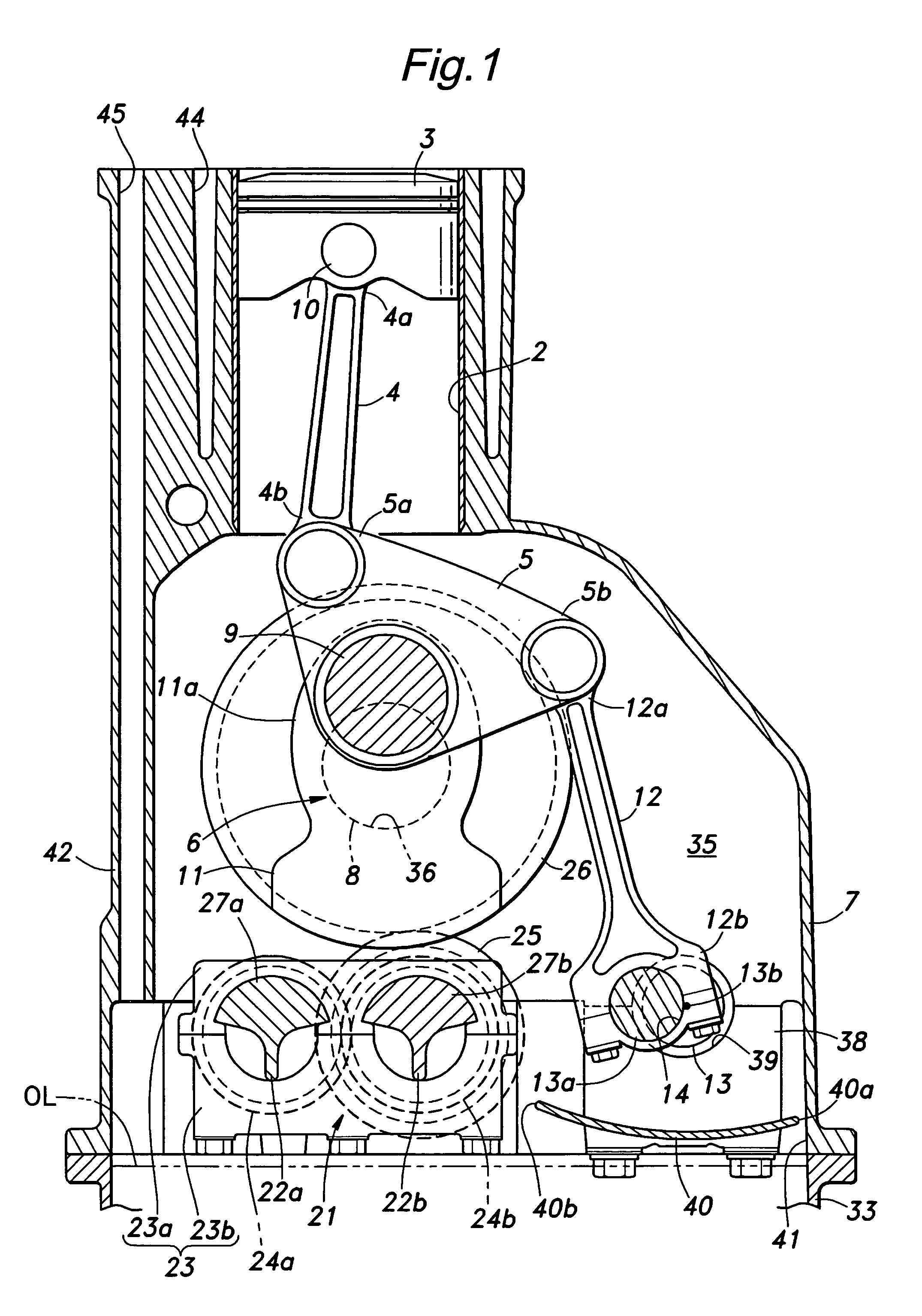
[0026]FIG. 1 is a schematic view of a variable stroke engine in the form of a variable compression ratio engine embodying the present invention with the cylinder head and other parts above the cylinder head omitted from the drawing. A cylinder 2 of this engine 1 slidably receives a piston 3 which is connected to a crankshaft 6 via a pair of links consisting of a first link 4 and a second link 5.

[0027]The crankshaft 6 is not different from that of a normal fixed compression ratio engine, and supports an intermediate part of the second link 5 which undergoes a rocking motion around a crankpin 9 of the crankshaft 6 offset from a crank journal 8 (rotational center of the crankshaft) supported within a crankcase 7. One end 5a of the second link 5 is connected to a big end 4b of the first link 4 having a small end 4a connected to a piston pin 10. The crankshaft 6 is provided with a counterweight 11 for canceling primarily the primary rotational oscillating component of the piston movement...


PUM


Abstract

Provided is a variable stroke property engine that can prevent an increase in the resistance to the engine owing to the contact between the variable stroke piston mechanism and lubricating oil. In a variable stroke property engine equipped with a variable piston stroke mechanism consisting of a plurality of links 4, 5 and 12, a baffle plate 40 is provided between the links and the oil surface of the lubricating oil received in an oil pan so that the links may be separated from the oil surface by the baffle plate and the lubricating oil is prevented from contacting the links. Thereby, an increase to the resistance to the movement of the links can be avoided.

Description

TECHNICAL FIELD[0001]The present invention relates to a variable stroke property engine, and in particular to a variable stroke property engine that can control an increase in the resistance owing to the contact between a variable stroke piston mechanism and lubricating oil in the oil pan.BACKGROUND OF THE INVENTION[0002]Variable stroke property engines comprising a plurality of links provided between the piston and crankshaft for varying the stroke of the piston by moving an end of one of the links that is connected to the engine main body are proposed in Japanese patent laid open publications Nos. 9-228858, 2004-138229 and 2004-150353.[0003]It is known that the resistance to the engine increases if the crankshaft contacts the lubricating oil in the oil pan. Particularly in the case of a variable stroke property engine, because there are a large number of moving parts such as links that move about within the crankcase, the contact between the lubricating oil and such moveable parts...

Claims


Application Information

Patent Timeline
Patent Type & Authority Patents(United States)
IPC IPC(8): F02B75/04F02B75/32
CPCF02B75/048F01M2011/0033F01M2011/005
Inventor MAEZURU, AKINORIIKOMA, KOICHIABE, KENJI
Owner HONDA MOTOR CO LTD
Why Eureka
Try Eureka