Efficient back-end channel matched filter (CMF)

a back-end channel and filter technology, applied in error prevention, amplitude demodulation, digital transmission, etc., can solve the problems of severe performance impairment, signal-to-noise ratio degradation, etc., and achieve optimal performance and efficient implementation of post- despreading channel matched filters

Inactive Publication Date: 2008-03-25
QUALCOMM INC
View PDF12 Cites 21 Cited by
  • Summary
  • Abstract
  • Description
  • Claims
  • Application Information

AI Technical Summary

Benefits of technology

[0009]The present invention uses despread and combined samples (passed through a despreading matched filter) to efficiently implement a post despreading channel matched filter. In addition, the estimation and channel profile evaluation is performed by a logic mechanism to determine the largest peak called cursor and produce the conjugated form of channel matched filter to be used on the despread and combined samples. This implementation represents a compact hardware block that does not need complex DSP or microprocessor computations as with previous matched channel filters. This symbol level (or “back-end”) channel matched filter structure enables the replacement of M multipliers (where M is the length of the channel matched filter) with a single shared multiplier. An efficient coefficient estimation mechanism provides for nearly optimal performance across a wide range of multipath channels for high-speed wireless data communication.
[0012]Embodiments of the present invention allow uncorrected input samples to pass to the despreading device and then are later corrected using a static set of channel matched filter coefficients. Estimation of the channel matched filter coefficients in conventional matched filters involve digital signal processor (DSP) or microprocessor computations. However, the present invention utilizes a hardware (HW) focused approach which is fast and efficient. Although the short spreading sequence present challenges in finding the earliest arriving path, i.e. the start of the channel response, two techniques are shown herein to efficiently unfold the channel response and find the cursor and earliest arriving path.
[0016]The channel estimator in typical embodiments produces the CIR estimate in a decision directed manner. The channel estimator can use a slicer that operates at approximately the cursor position to produce the channel impulse response (CIR) estimate. The slicer can be operated over a plurality of probing intervals for averaging to reduce variance of the CIR estimate. Further, the output of the channel estimator can be processed by one or more of the operations comprising complex conjugation, truncation and scaling to produce the CIR estimate to improve the overall result of the CMF.

Problems solved by technology

Along each path, components of the transmitted signal undergo random attenuation and phase offset, and may add destructively or constructively with each other at the receiver; this multipath effect can cause degradation of signal-to-noise ratio (SNR), resulting in severe performance impairment.
Implementing short packet wireless data communications over a wireless channel, such as that specified in IEEE 802.11, poses challenges in combating these multipath problems.

Method used


Image

  • Efficient back-end channel matched filter (CMF)
  • Efficient back-end channel matched filter (CMF)
  • Efficient back-end channel matched filter (CMF)

Examples


Embodiment Construction

[0025]In the following description of the preferred embodiment, reference is made to the accompanying drawings which form a part hereof, and in which is shown by way of illustration specific embodiments in which the invention may be practiced. It is to be understood that other embodiments may be utilized and structural changes may be made without departing from the scope of the present invention.

1. Back-End Channel Matched Filter Overview

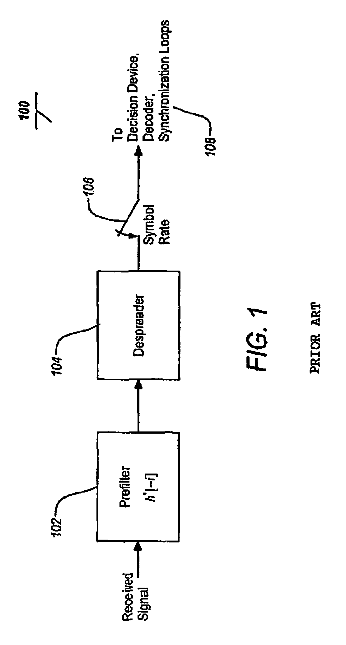
[0026]The conventional, front-end CMF of FIG. 1 represents a concatenation of two linear time-invariant operations, since the despreader can be consider as a finite-impulse response (FIR) filter with a response equal to the time-reversal version of the spreading sequence. Hence, the connection can be interchanged without altering the overall response of the concatenated system.

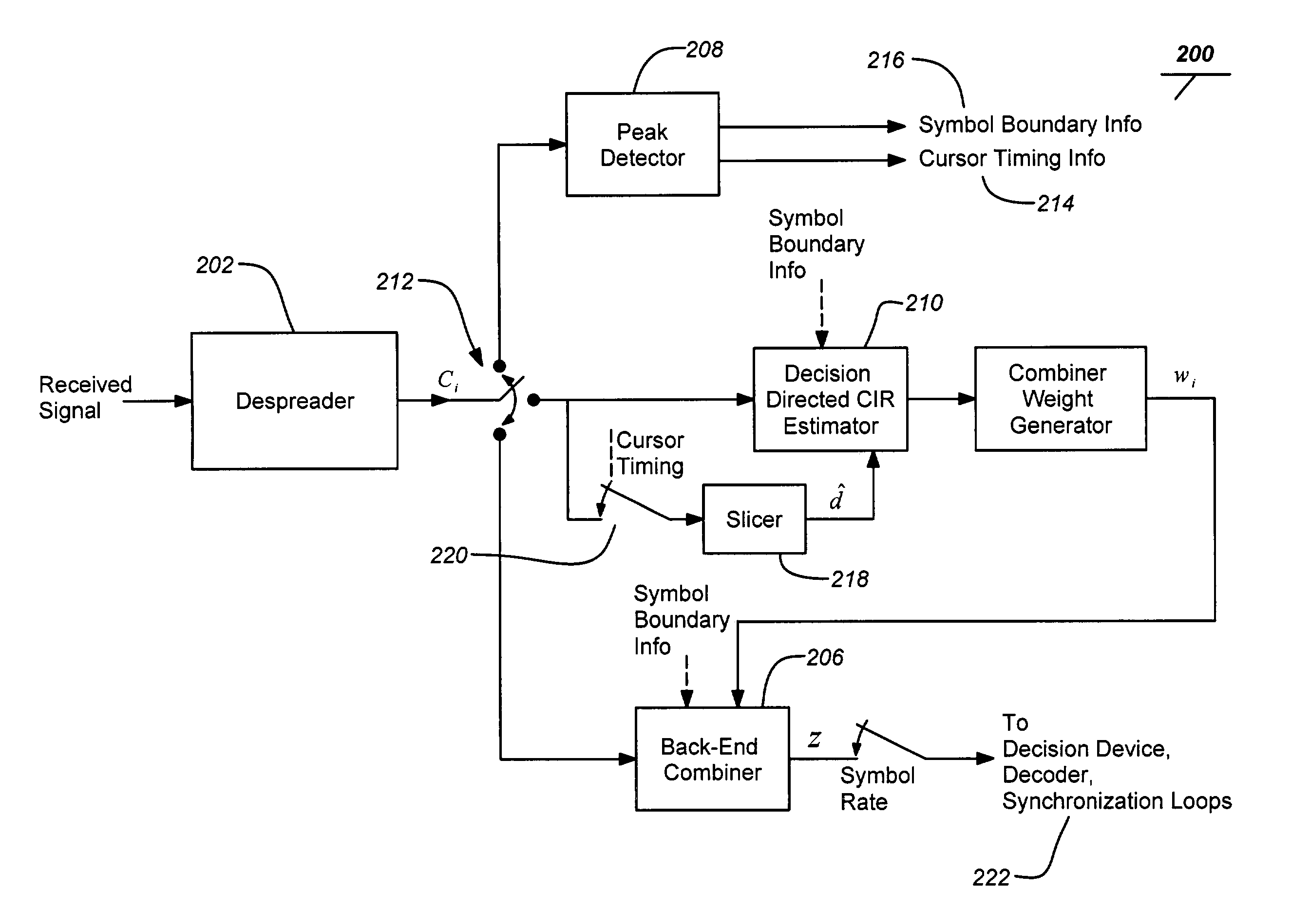
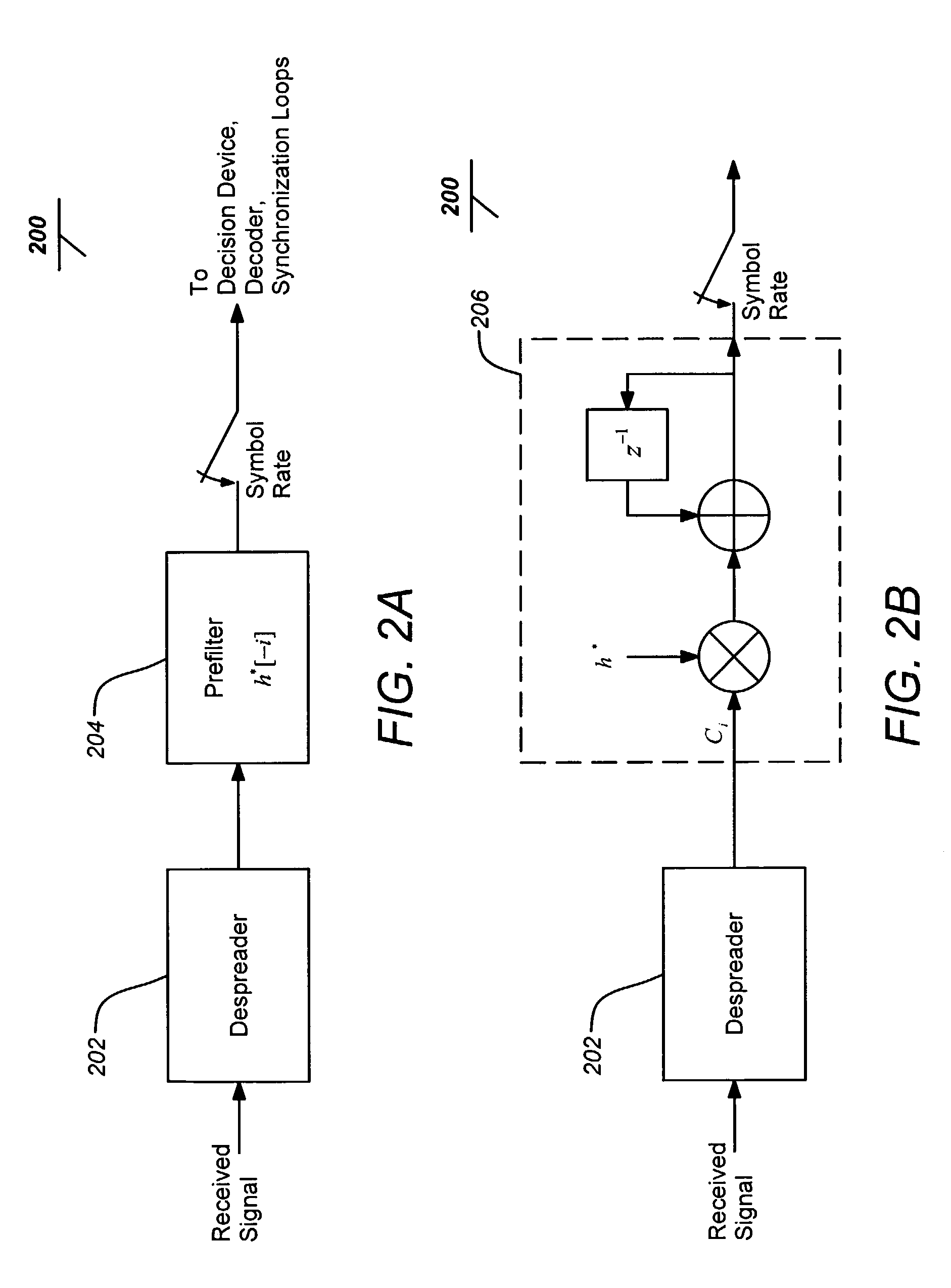
[0027]FIGS. 2A and 2B are block diagrams of a typical back-end channel matched filter implementation of the present invention. The back-end CMF architecture 200 with the filte...


PUM


Abstract

An efficient method and apparatus for implementing a back-end channel matched filter in a receiver is disclosed. A typical channel matched filter embodiment includes a peak detector for establishing processing synchronization from a despread signal, a channel estimator producing a channel impulse response (CIR) estimate from the despread signal based on the synchronization by the peak detector and a back-end symbol combiner coherently combining dominant multipath components of the despread signal by weights based on the CIR estimate based on the synchronization by the peak detector to generate a decision variable. In a digital spread spectrum implementation, the despread signal operated on by the channel matched filter has been previously been correlated with a spreading sequence replica.

Description

BACKGROUND[0001]1. Field[0002]The present invention relates to systems and methods for implementing channel matched filter (CMF) circuits, and particularly for implementing channel matched filter circuits to facilitate spread spectrum reception in a wireless local area network (LAN). For example, the present invention finds application in the Institute of Electrical and Electronics Engineers (IEEE) 802.11 standard for wireless LANs using spread spectrum.[0003]2. Description[0004]In a typical wireless communications system, the transmitted signal travels through multiple propagation paths before arriving at the receiver. Along each path, components of the transmitted signal undergo random attenuation and phase offset, and may add destructively or constructively with each other at the receiver; this multipath effect can cause degradation of signal-to-noise ratio (SNR), resulting in severe performance impairment. Therefore, it is desirable to appropriately combine these multipath compo...

Claims


Application Information

Patent Timeline
Patent Type & Authority Patents(United States)
IPC IPC(8): H04B1/00H04L1/00H04B1/707
CPCH04B1/7093H04B1/712
Inventor GLAZKO, SERGUEI A.HURT, JAMES Y.LAI, KUEI-CHIANG
Owner QUALCOMM INC
Why Eureka
Try Eureka