
Flexible thin printed battery and device and method of manufacturing same

a thin battery and printed battery technology, applied in the direction of cell components, final product manufacturing, sustainable manufacturing/processing, etc., can solve the problems of low cost per unit application, low manufacturing efficiency, and high cost of high throughput equipment,

Active Publication Date: 2008-03-25
ENERGIZER BRANDS
View PDF23 Cites 56 Cited by
  • Summary
  • Abstract
  • Description
  • Claims
  • Application Information

AI Technical Summary

Benefits of technology

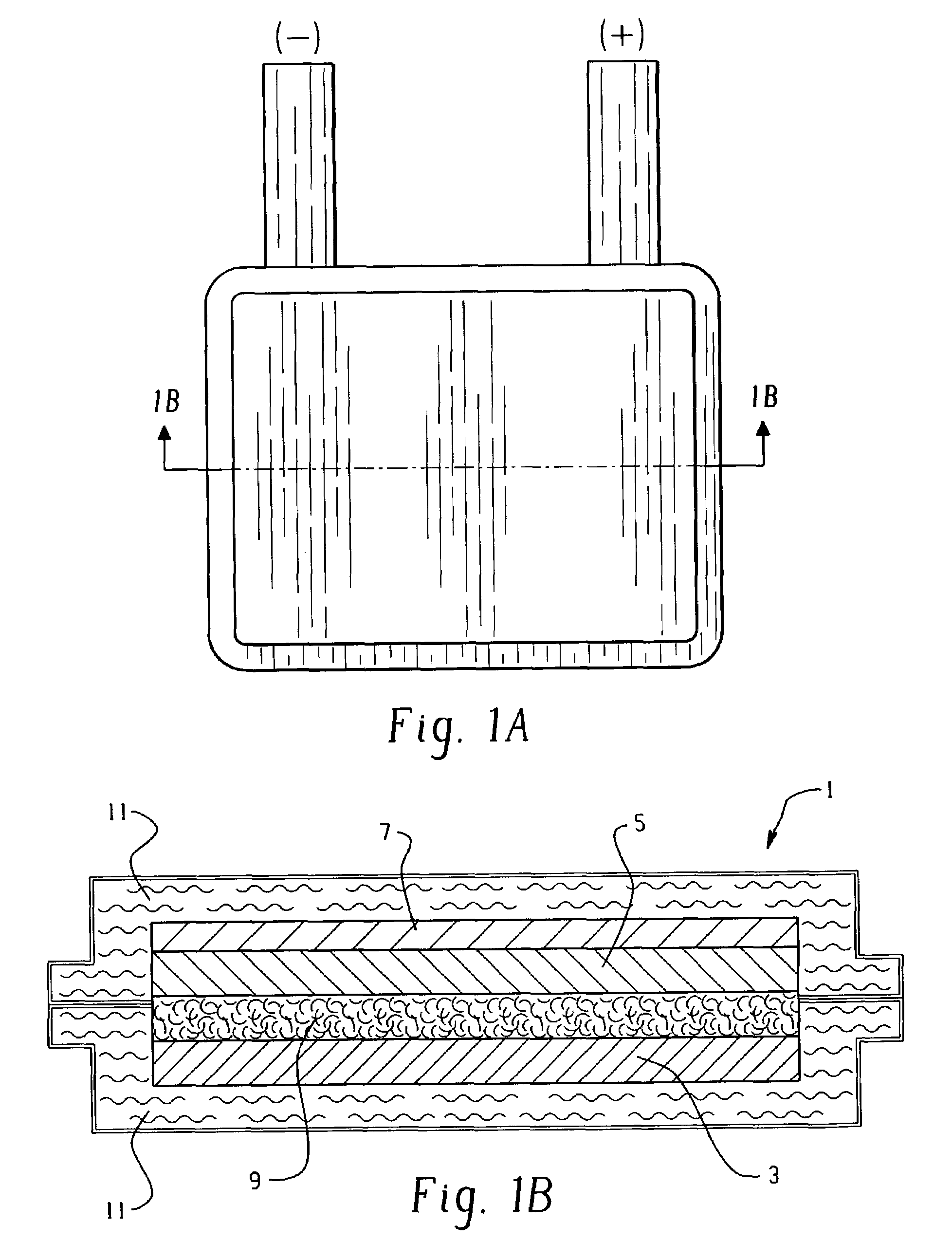
The patent describes a thin, flexible printed battery that can be used to power devices. The battery has a printed electrode and an electrolyte contained within a sealed housing. The battery also has external contacts that provide current to the battery. The electrodes can be arranged in a coplanar or cofacial manner. The battery is made using a flexible nonconductive polymer material that can be joined together to form a battery package. The patent also describes different aspects of the printed battery that can be used with different cell chemistries without changing the scope of the patent.

Problems solved by technology

These techniques tend to require relatively costly and complex equipment and do not lend themselves to a high throughput inexpensive manufacturing process.
Lithium-based technologies are not an attractive power source for such low cost per unit applications.

Method used

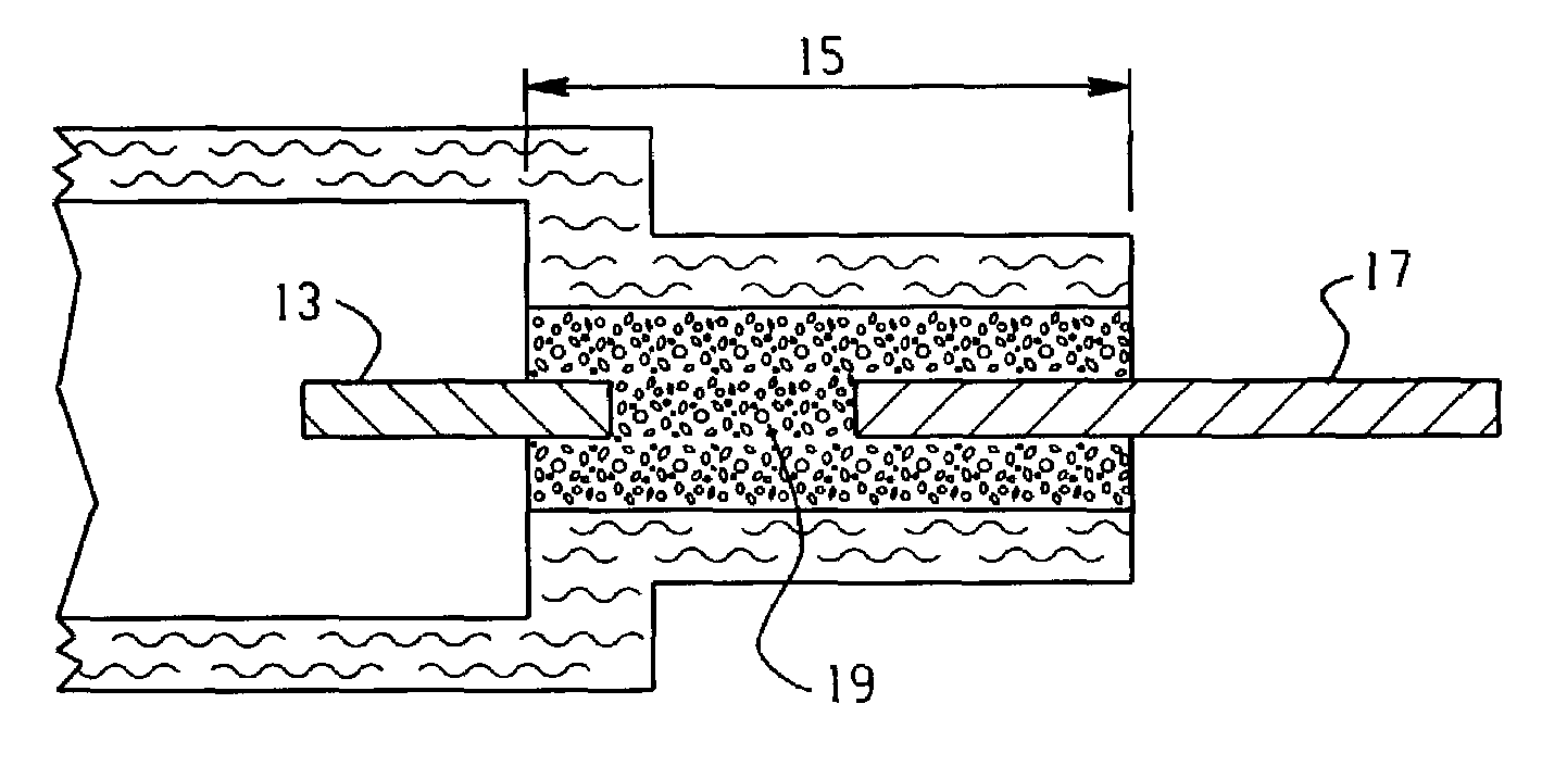

Image

  • Flexible thin printed battery and device and method of manufacturing same
  • Flexible thin printed battery and device and method of manufacturing same
  • Flexible thin printed battery and device and method of manufacturing same

Examples


example 1

All Percents are by Weight Unless Otherwise Indicated

[0119]Cells were made according to this example. The anode ink wet formulation was 9.6 percent zinc acetate dihydrate, 31.7 percent water, 1.3 percent PVP (molecular weight of 2.2 to 2.8 million) and 57.4 percent zinc dust. The zinc ink was made by first combining the zinc acetate dihydrate obtained from Aldrich Chemical Company with water to form an aqueous solution. PVP was added to the aqueous solution to make a viscous salt-polymer solution. Zinc dust added and the mixture was stirred until homogeneous. The zinc dust was leaded with 0.16 percent lead. The zinc dust had a Microtrac average volumetric particle size, or d(50) value of about 10 microns. The mixture was allowed to stand to achieve the appropriate thickness, about 90 to 120 minutes. An anode was then screen printed by hand. The anode substrate was the inner heat sealable surface of a flexible polymer and metal laminate packaging material available from Pharma Center...

example 2

[0124]Co-planar electrode assembly cells were constructed according to this example. An anode was printed using the same anode ink formulation and substrate as in Example 1, and a 0.002 inch thick zinc mesh anode current collector as in Example 1 was affixed to the substrate in the same manner as in Example 1. The anode 34 was screen printed to a size of 50.4 millimeters×6.8 millimeters with an average thickness of 109 millimeters. The cathode current collector and cathode were stenciled using the same formulation as in Example 1 onto the same substrate as the anode to form a co-planar electrode arrangement. The cathode current collector 35 was stenciled to a size of 40 millimeters×27 millimeters×0.036 millimeters, while the cathode ink 37 was stenciled onto the current collector with a thickness of 0.166 millimeters. See FIG. 9. The gap between the cathode and the anode was 2.0 millimeters. The electrode surfaces were wetted up with the same electrolyte as in Example 1, and the sam...

example 3

[0127]Co-facial electrode assembly cells were constructed as follows. A zinc mesh anode was utilized in the cells of this example, consisting of a 0.005 inch thick piece of zinc mesh available from Delkar Corporation. The mesh was cut to 39 millimeters×37 millimeters and adhered to the same substrate material as in Examples 1 and 2. The anode current collector was formed from this zinc mesh also and adhered to the substrate in the same manner.

[0128]The cathode current collector for the cells of this example used the same carbon ink as in Example 1, and was stenciled as in Example 1 to a size of 40 millimeters×38 millimeters with an average thickness of 0.052 millimeters on the same substrate material as in Example 1. The cathode ink was the same ink formulation as in Example 1, and was stenciled onto the collector as in Example 1 to an average thickness of 0.149 millimeters. The same separator material was used as in Example 1 and the same electrolyte as in Example 1 was introduced ...


PUM

PropertyMeasurementUnit
thickaaaaaaaaaa
thickaaaaaaaaaa
particle size d(50)aaaaaaaaaa

Abstract

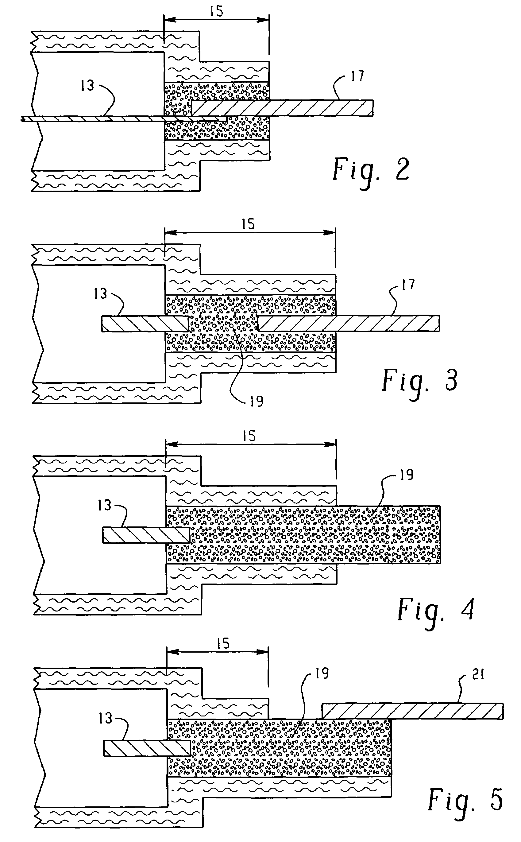
A flat, flexible electrochemical cell is provided. The within invention describes various aspects of the flat, flexible electrochemical cell. A printed anode is provided that obviates the need for a discrete anode current collector, thereby reducing the size of the battery. An advantageous electrolyte is provided that enables the use of a metallic cathode current collector, thereby improving the performance of the battery. Printable gelled electrolytes and separators are provided, enabling the construction of both co-facial and co-planar batteries. Cell contacts are provided that reduce the potential for electrolyte creepage in the flat, flexible electrochemical cells of the within invention.

Description

RELATED APPLICATIONS[0001]This application claims benefit under 35 USC 119(e) to the following U.S. provisional patent applications: U.S. Pat. Application No. 60 / 356,407, U.S. Pat. Application No. 60 / 356,236, U.S. Pat. Application No. 60 / 356,213, U.S. Pat. Application No. 60 / 356,406, U.S. Pat. Application No. 60 / 356,583, U.S. Pat. Application No. 60 / 356,247, U.S. Pat. Application No. 60 / 356,266, and U.S. Pat. Application No. 60 / 356,584, all filed on Feb. 12, 2002 and pending.FIELD OF THE INVENTION[0002]This invention relates to a flexible thin battery and device and a method for making such a battery and device. More specifically, this invention relates to a flexible thin printed battery wherein one or more of the electrodes are printed onto a flexible substrate using a printable ink, and to devices powered by such batteries.BACKGROUND OF THE INVENTION[0003]Flexible planar thin batteries utilizing lithium-based chemistries are known wherein the electrodes are formulated by the depos...

Claims


Application Information

Patent Timeline
Patent Type & Authority Patents(United States)
IPC IPC(8): H01M6/00H01M2/08H01M2/20H01M4/66B05D3/02B05D3/06H01M4/02H01M4/04H01M4/06H01M4/08H01M4/24H01M4/26H01M4/50H01M4/62H01M4/70H01M6/02H01M6/04H01M6/06H01M6/12H01M6/22H01M6/40H01M50/121H01M50/42H01M50/463H01M50/497
CPCH01M2/0257H01M2/0277H01M2/1653H01M2/18H01M4/0404H01M4/0414H01M4/06H01M4/08H01M4/244H01M4/26H01M4/50H01M4/62H01M4/623H01M4/667H01M6/045H01M6/12H01M6/22H01M6/40Y10T29/49108H01M4/625H01M4/663H01M2004/021H01M2004/027H01M2004/028H01M2300/0002H01M2300/0014H01M2300/0085Y02E60/124Y10T29/49114Y10T29/49115Y10T29/4911H01M2/0275Y02E60/10H01M50/463Y02P70/50H01M50/121H01M50/497H01M50/42
Inventor SCHUBERT, MARK A.ZHANG, JINGZHENG, GUANGHONGFEDDRIX, FRANK H.LANGAN, RICHARD A.TUDRON, FRANK B.TUCHOLSKI, GARY R.HILMI, ABDELKADERBAILEY, JOHN C.WEBBER, ANDREW
Owner ENERGIZER BRANDS
Learn More