
Reflection free launcher for electromagnetic guide wire

a launcher and electromagnetic guide wire technology, applied in the direction of instruments, machines/engines, using reradiation, etc., can solve the problems of obscuring the desired short-range echoes, casting reflections from the aperture, and being too large for many practical applications, so as to achieve compact size and easy measurement of short-range echoes

Inactive Publication Date: 2008-03-18
MCEWAN TECH
View PDF12 Cites 601 Cited by
  • Summary
  • Abstract
  • Description
  • Claims
  • Application Information

AI Technical Summary

Benefits of technology

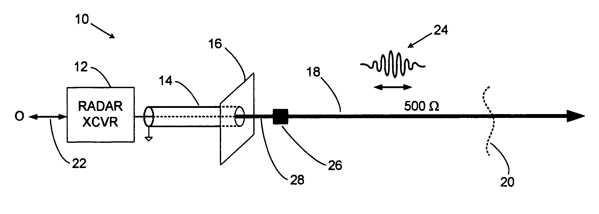
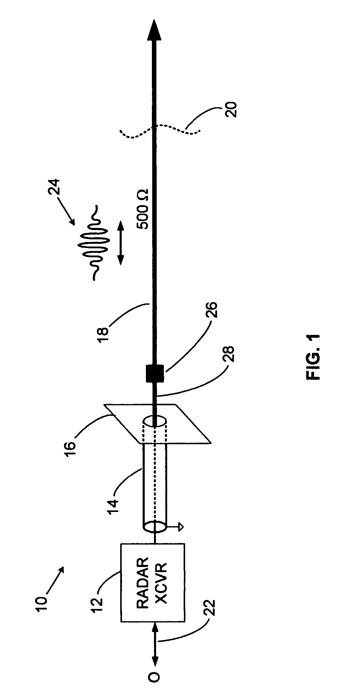
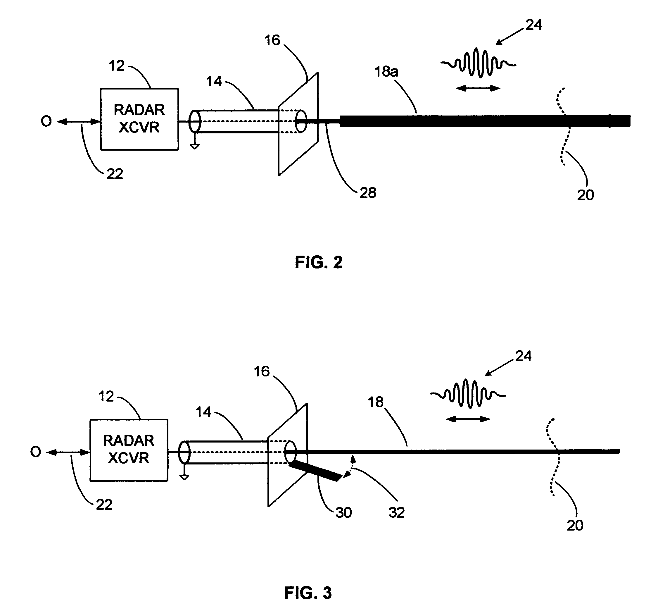
"The present invention provides a reflection-free electromagnetic guide wire launcher for GWR sensors. It includes a transition device and an impedance matching element to convert from a dual conductor transmission line to a single conductor electromagnetic guide wire. The impedance matching element can be a reflector, a guide wire of larger diameter, or a resonant stub. The launcher produces no reflections and is compact for insertion through small apertures. The invention also provides a procedure for launching an electromagnetic pulse onto a guide wire and a guided wave radar sensor. The technical effects include improved measurement of short range echoes and compact size for easy insertion."

Problems solved by technology

However, guide wires, or equivalently, larger diameter stainless steel rod-like probes are rarely coated in modern guided wave radar (GWR) applications such as tank level sensing.
While the horn is simple, it is often too large for many practical applications, e.g., tank fill level sensing, where small openings in the tank are often the only available apertures through which a GWR probe can be inserted.
Another limitation to the horn is it often casts reflections from its aperture since the transition from the coaxial geometry at the aperture to the open geometry of the guide wire introduces an impedance discontinuity.
Unfortunately, the large reflection from the launcher plate obscures desired short-range echoes.
Thus, it is difficult to sense a full condition in a tank, or to accurately measure tanks levels when nearly full.

Method used


Image

  • Reflection free launcher for electromagnetic guide wire
  • Reflection free launcher for electromagnetic guide wire
  • Reflection free launcher for electromagnetic guide wire

Examples


Embodiment Construction

[0033]A detailed description of the present invention is provided below with reference to the figures. While illustrative component values and circuit parameters are given, other embodiments can be constructed with other component values and circuit parameters. All U.S. Patents and copending U.S. applications cited herein are herein incorporated by reference.

General Description

[0034]The present invention overcomes the limitations of the various prior guided wave radar launchers by including an impedance matching element based on reflection techniques. In contrast, prior impedance matching techniques include (1) absorptive matching using resistors, as seen in the above-cited '059 patent to McEwan, and (2) distributed transformer matching using a horn or blades, as seen in the above-cited Goubau, Ross and McEwan patents. Reflection matching is based on creating a matching reflection of equal magnitude and opposite phase to cancel the unwanted reflection produced by the launcher impeda...


PUM


Abstract

Guided wave radar (GWR) pulses are launched onto an electromagnetic guide wire using a compact launcher that includes an impedance matching element. The impedance matching element produces reflections that cancel launcher reflections. Short range echoes can be accurately detected after impedance matching. GWR operation in small tanks and in tanks containing low dielectric constant materials, such as propane, can be enhanced with the compact impedance-matched launcher.

Description

BACKGROUND OF THE INVENTION[0001]1. Field of the Invention[0002]The present invention relates to a pulse launcher for single wire transmission lines adapted to pulsed electromagnetic sensors, and more particularly to fluid and material level sensors employing Guided Wave Radar (GWR) reflectometers. These sensors can be used for determining or controlling the fill-level of a tank, vat, irrigation ditch, silo, pile, or conveyor.[0003]2. Description of Related Art[0004]Propagation of electromagnetic waves along a single wire transmission line, also known as an electromagnetic guide, or guide wire, was first theorized by A. Sommerfeld in 1899. Sommerfeld's transmission line relies on a resistively lossy conductor to slow the wave slightly. Slower propagation, on the order of 99% of the speed of light, is required to retain the propagating fields proximal to the guide wire. In 1954, G. Goubau disclosed in U.S. Pat. No. 2,685,068, “Surface Wave Transmission Line,” another method to slow p...

Claims


Application Information

Patent Timeline
Patent Type & Authority Patents(United States)
IPC IPC(8): G01S13/08G01F23/284
CPCG01F23/284
Inventor MCEWAN, THOMAS EDWARD
Owner MCEWAN TECH
Learn More