
Child car seat

Inactive Publication Date: 2008-03-18
RECARO CHILD SAFETY
View PDF12 Cites 24 Cited by
  • Summary
  • Abstract
  • Description
  • Claims
  • Application Information

AI Technical Summary

Benefits of technology

[0009]This creates the possibility of relative movement between the seat shell on the one hand and the sitting surface or backrest on the other, making it possible to adjust the inclination of the sitting surface and / or backrest without thereby changing the position of the seat shell with respect to the vehicle-inherent seat. For this reason, such a child seat is suitable for any type of attachment to a vehicle-inherent seat—both using a vehicle-inherent belt and by means of so-called ISOFIX tabs, which can be latched in anchor points provided for this purpose in the region of the vehicle seat. The latter is of interest primarily because if a total of four mounting tabs is provided—two on the front of the seat and two on the back—the child seat can be mounted on the vehicle-inherent ISOFIX anchorages alternatively either in the direction of travel or opposite the direction of travel, as is mandatory for example in Sweden for children weighing up to 18 kg. Because the seat shall has a sitting-surface region, a backrest region and lateral bounds, for example armrests and / or lateral head supports, from a purely external standpoint it conforms to the usual construction of a child seat in which the sitting-surface region and backrest regions serve primarily to support the seat on a vehicle-inherent seat and to provide anchor points or bearing or guide points for the moving parts of the seat. On the other hand, it is not necessary for the armrests and / or lateral head supports to be carried along as the inclination is adjusted, so to increase stability these elements are connected to the body of the seat shell. Since the outer seat shell per se is rigidly implemented, the child seat as a whole is imparted the necessary stiffness to hold the moving parts of the seat, and also, in particular, a child located in the seat, securely in place despite any increased accelerative or decelerative or lateral forces. A manually operable adjusting device for adjusting the inclination is provided on the seat. Its function is, by virtue of being coupled to a moving part of the seat on the one hand and to the seat shell on the other, to exert an effect on the relative position of the two; moreover, the adjusting device should be capable of locking a relative position once said position has been set, preferably in such fashion that no automatic adjustment of any kind can occur even under strong accelerative or decelerative forces. This can be achieved for example by means of a stop mechanism which at certain relative positions creates a form-locking connection that cannot be broken without releasing the stop element concerned. Also conceivable, however, is a clamping and / or self-locking mechanism that can be actuated in arbitrary intermediate positions of the movable seat element. With such an adjusting device, the necessary manipulations are reduced to such an extent that adjustment is possible even when the vehicle is in motion.
[0024]Of not inconsiderable importance to the stability of the inventive seat is to reinforce an adjustable seat portion with ribs that extend around it at least regionally, or even a frame. This enables (weight) forces that are exerted areally on the movable portion of the seat to be collected along certain lines and passed on—optionally via the edge of the seat—to attachment points, particularly bearing and / or guide points, thus preventing local overstressing of a rather two-dimensional seat portion. Such stiffening ribs or frames are preferably disposed on the bottom or back side, facing away from the child, of a rather two-dimensional seat element. Stiffening ribs are preferably made of plastic and integrated with the seat element concerned; a frame can be implemented for example in the form of tubing, since a tube has an optimum stability-to-weight ratio.

Problems solved by technology

These disadvantages of the described prior art have given rise to the problem initiating the invention, that of improving a child car seat of this kind in such fashion that it is possible with minimal structural expenditure to adjust the seat inclination without having to lift the child out of the seat for the purpose.

Method used


Image

  • Child car seat
  • Child car seat
  • Child car seat

Examples


Embodiment Construction

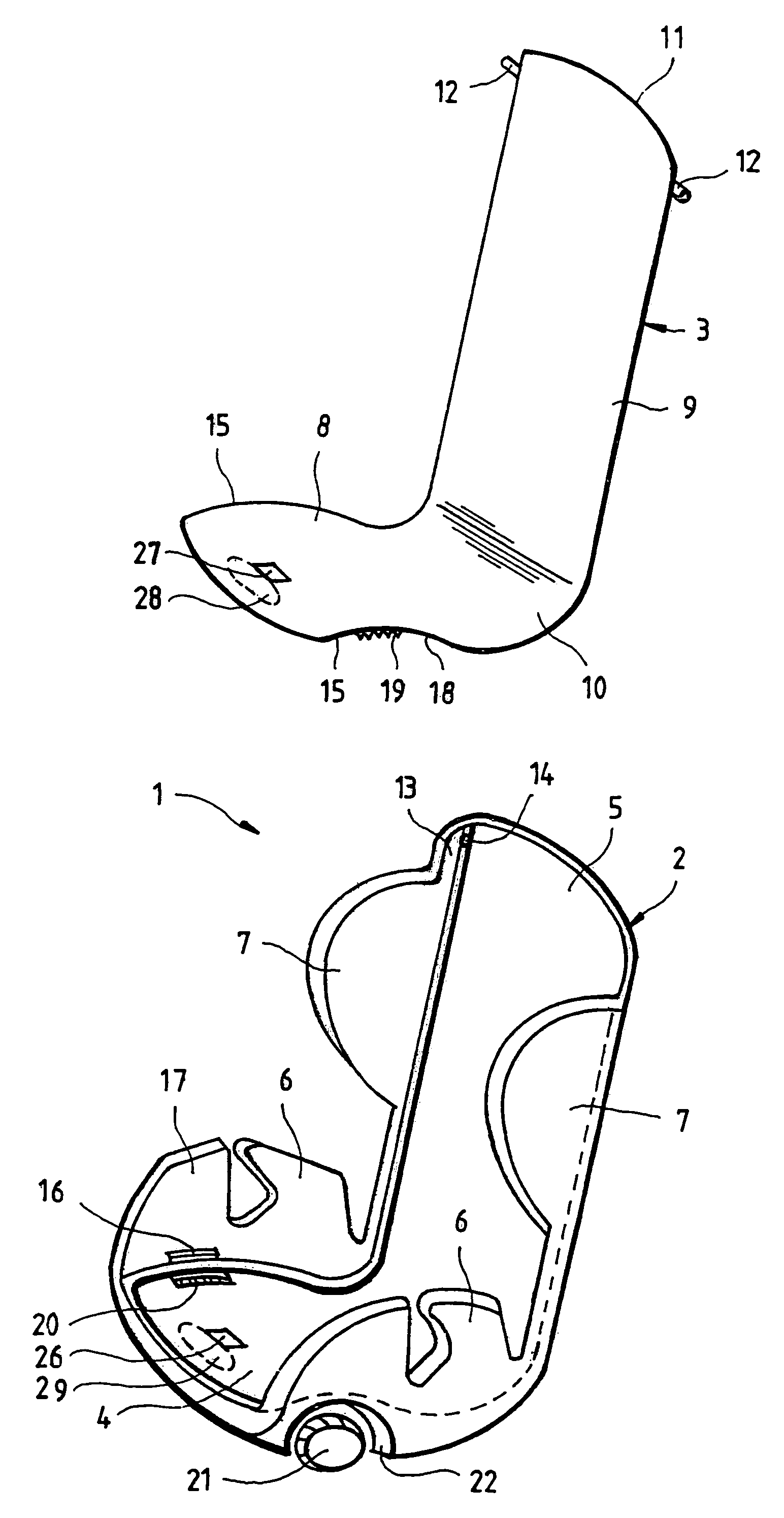
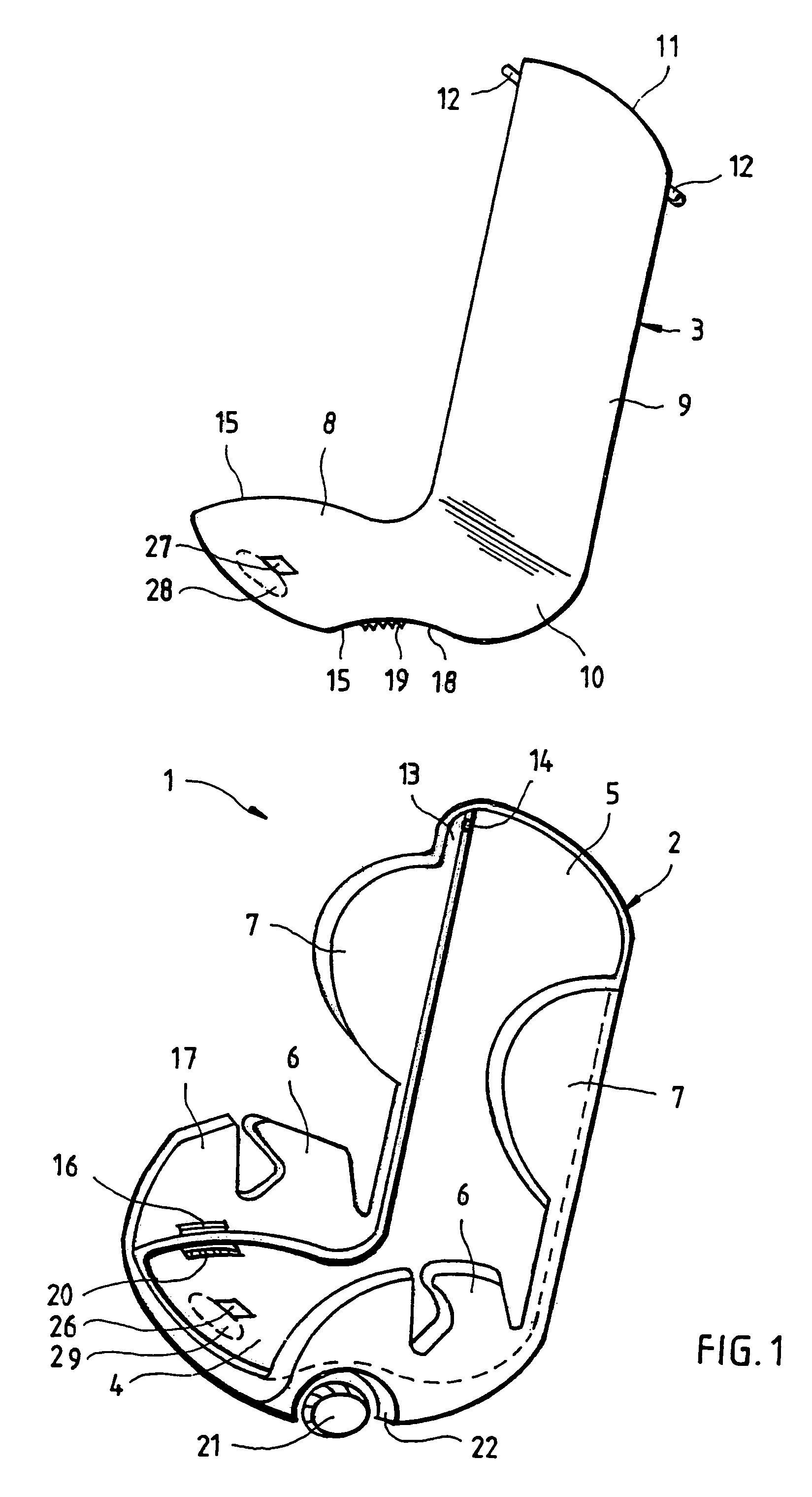
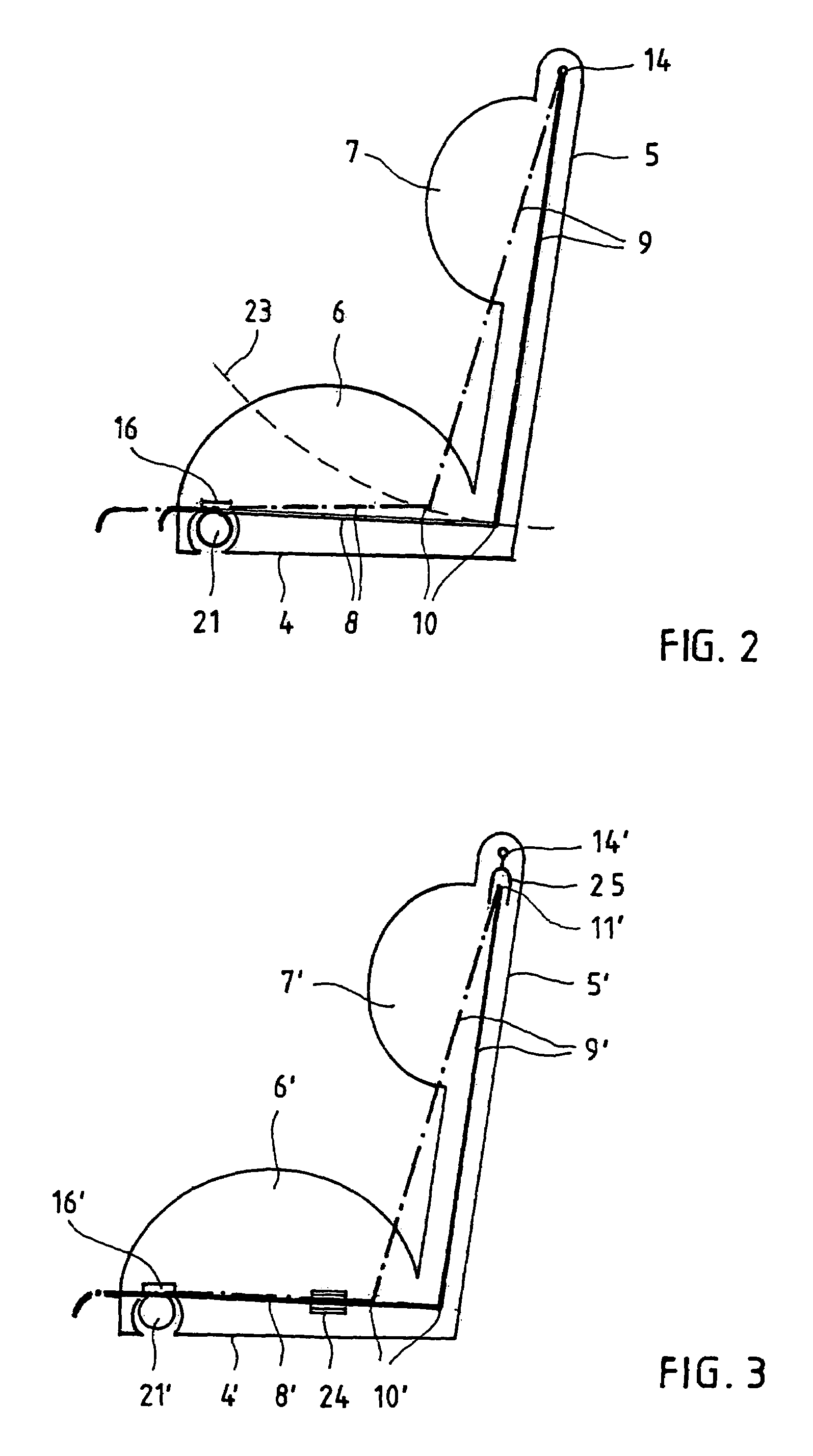
[0034]The child car seat 1 of FIG. 1 is basically composed of two parts: a seat shell 2 and an insert 3 movably received therein.

[0035]The seat shell 2 roughly corresponds in its outer dimensions to an ordinary commercial child car seat. It comprises a sitting-surface region 4, a backrest region 5, two armrests 6 and two lateral head supports 7. In contrast to the case with an ordinary commercial child car seat, however, neither sitting-surface region 4 nor backrest region 5 is designed for direct use; in particular, they are not padded in any way.

[0036]Provided instead is the insert 3, a planar part having a curved profile roughly corresponding to a roughly horizontal sitting surface 8 and a roughly vertical backrest 9. The transitional region 10 between the two sections 8, 9 can be gently curved. The insert 3 is shaped with respect to both its circumference and its curvature such that it conforms as exactly as possible to the sitting-surface and backrest regions 4, 5 of the seat s...


PUM


Abstract

The invention is directed to a child car seat, composed ofa) a seat shell, comprising a bottom sitting region with at least one bottom stand surface to be stood on a seat of a vehicle, a backrest region extending upwardly from the sitting region and having at least one outer surface to be leaned against the backrest of the vehicle seat, and lateral surfaces, for example lateral armrests, shoulder supports and / or head supports, for limiting the lateral range of movement of a child, at least that portion of the backrest region that comprises a rear leaning surface being rigidly connected to the sitting region comprising a bottom stand surface, andb) a rather two-dimensional seat element, comprising a sitting surface and / or backrest that is / are disposed on the inner side, turned toward the child, of the seat shell and is / are adjustable with respect thereto in terms of inclination and position and is / are lockable in a plurality of different inclinations and / or positions by means of a manually operable device on the seat having a coupling to the adjustable, rather two-dimensional seat element on the one hand and to the seat shell on the other.

Description

BACKGROUND OF THE INVENTION [0001]1. Field of the Invention[0002]The invention is directed to a child car seat, composed of, on the one hand, a seat shell comprising a lower sitting region with a bottom stand surface to be stood on a seat of a vehicle, a backrest region extending upwardly from the sitting region and having an outer surface to be leaned against the backrest of the vehicle seat, and lateral surfaces, for example lateral armrests, shoulder supports and / or head supports, for limiting the lateral range of movement of a child, at least that portion of the backrest region that comprises the rear leaning surface being rigidly connected to the sitting region comprising the bottom stand surface; and on the other hand, a seat element comprising a sitting surface and / or backrest that is / are disposed on the inner side, turned toward the child, of the seat shell and is / are adjustable with respect thereto in terms of inclination and / or position. The bottom stand surface can be con...

Claims


Application Information

Patent Timeline
IPC IPC(8): A47C7/02A47D1/10
CPCB60N2/2821B60N2/286B60N2/2872B60N2/2878
Inventor KESPOHL, HORST-GUNTHER
Owner RECARO CHILD SAFETY
Learn More