
Sidestream gas sampling system with detachable sample cell

a sampling system and sample cell technology, applied in the field of detachable sample cells for sidestream respiratory gas sampling systems, can solve the problems of affecting the quality of patient care, and the risk of significant capnographic waveform and lower end-tidal values, so as to reduce the need for costly preventive maintenance

Inactive Publication Date: 2008-03-11
RIC INVESTMENTS LLC
View PDF19 Cites 30 Cited by
  • Summary
  • Abstract
  • Description
  • Claims
  • Application Information

AI Technical Summary

Benefits of technology

[0016]Accordingly, it is an object of the present invention to provide a sidestream gas sampling system and a sample cell for use in such a system that overcomes the shortcomings of conventional sidestream gas sampling systems. This object is achieved according to one embodiment of the present invention by providing a sidestream gas sampling system that includes a sidestream gas measurement assembly and a sample cell that is configured to removeably attach to the sidestream gas measurement assembly. More specifically, the sample cell incorporating the teachings of the present invention is configured to be received by and readily and removably interconnected with and disconnected from a corresponding receptacle in the housing of the sidestream gas measurement assembly. The use of a removable sample cell obviates or minimizes the need for costly preventive maintenance required by conventional sidestream gas monitoring systems. Instead, the sample cell of the present invention is merely discarded and replaced with a new sample cell as needed.
[0018]A further embodiment of the present invention contemplates providing a sample cell that includes an interconnection element disposed on a body of the sample cell. The interconnection element is configured to engage a corresponding feature of a sidestream gas measurement assembly that is configured to at least partially receive the sample cell. In this way, the sample cell is securely affixed to the sidestream gas measurement assembly such that the window is in precise optical alignment with the gas measurement components in the sidestream gas measurement assembly.

Problems solved by technology

This results in a drier sampling tube but with the inherent risk of significant distortion of the capnographic waveform and lower end-tidal values.
However, there is a possibility of an accumulation of condensate and / or patient secretions in this configuration for a sidestream sampling system.
Condensation from a humidified sample gas, in combination with patient secretions, can block and contaminate the sampling tube, which may necessitate frequent replacement thereof.
The effectiveness of water traps and water filters vary between manufacturers, but no water trap or water filter is immune to eventual clogging and distortion of the capnographic waveform, particularly if preventive maintenance is inadequate.
Additionally, sources of leaks external to the gas monitor, such as loose fittings, cracked or slit sampling tubes, cracked sample filters, and cracked airway adapters, along with sources of leaks internal to the monitor, such as partial disconnection, are known to cause significant artifact in the capnogram output by conventional sidestream gas sampling systems.
Leaks and obstructions can occur at any of the numerous connection points and tubes within a sidestream gas sampling system.
As it may be difficult or impossible to calibrate for such artifacts, leaks, and obstructions, the capnographic waveforms and end-tidal measurements that are generated by use of sidestream analyzers may provide values that are significantly different from the actual values, which may, in turn, pose a potential hazard to the patient.
While more recent sidestream gas sampling system designs employ sampling ports that are located in the center of the adapter and, thus, along the flow path therethrough rather than at a wall thereof and, therefore, are less likely to aspirate secretions within a patient's respiration, they are still susceptible to the problems outlined above.
These problems are further exacerbated by the fact that the sample cells of sidestream analyzers are reusable and nondisposable, with windows that are formed from sapphire or other expensive materials.
Thus, over time, condensation and contamination are likely to build up within such sample cells, reducing their performance over time.
As a result, following the cleaning of such a sample cell, the accuracy of measurements obtained therewith diminishes over time.

Method used


Image

  • Sidestream gas sampling system with detachable sample cell
  • Sidestream gas sampling system with detachable sample cell
  • Sidestream gas sampling system with detachable sample cell

Examples


first embodiment

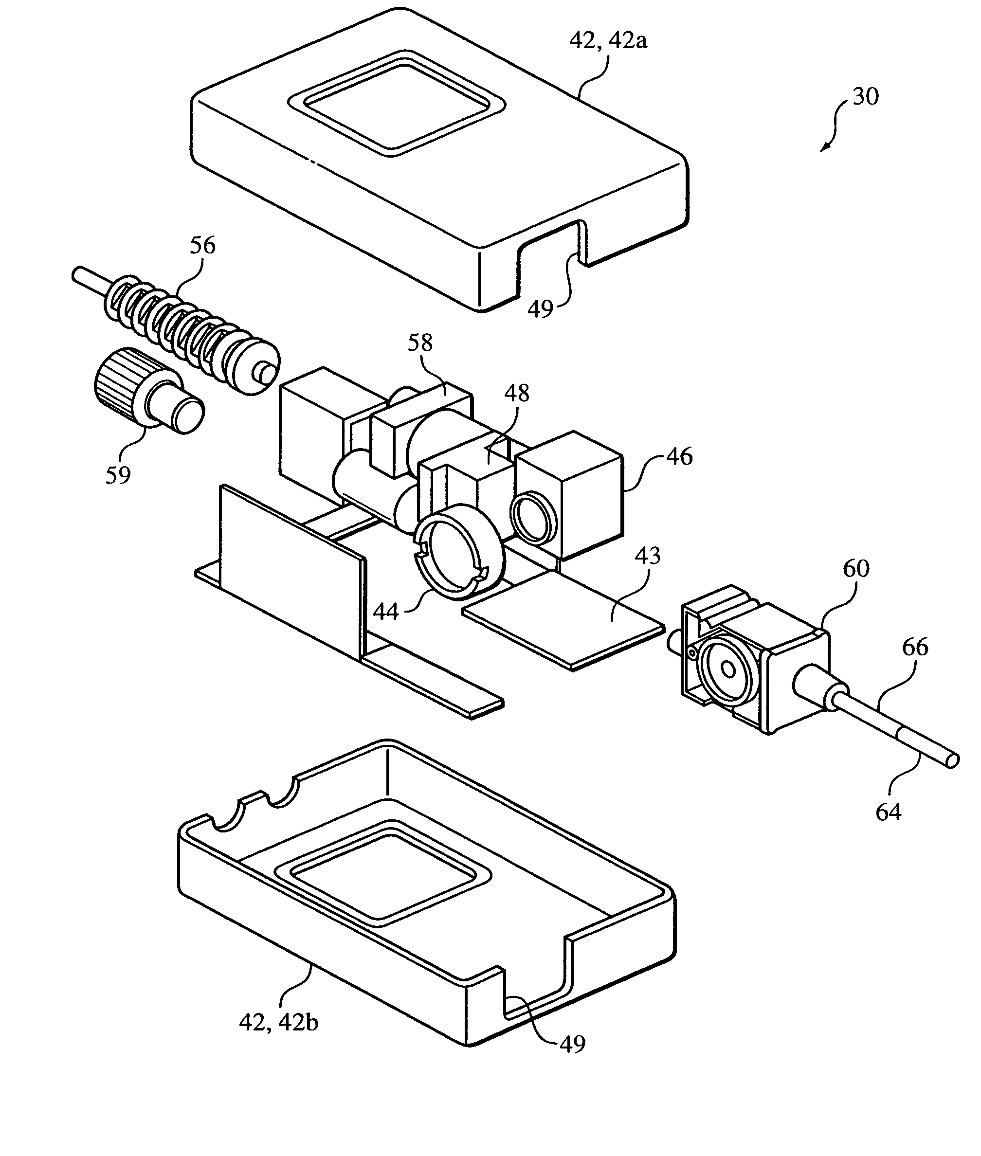
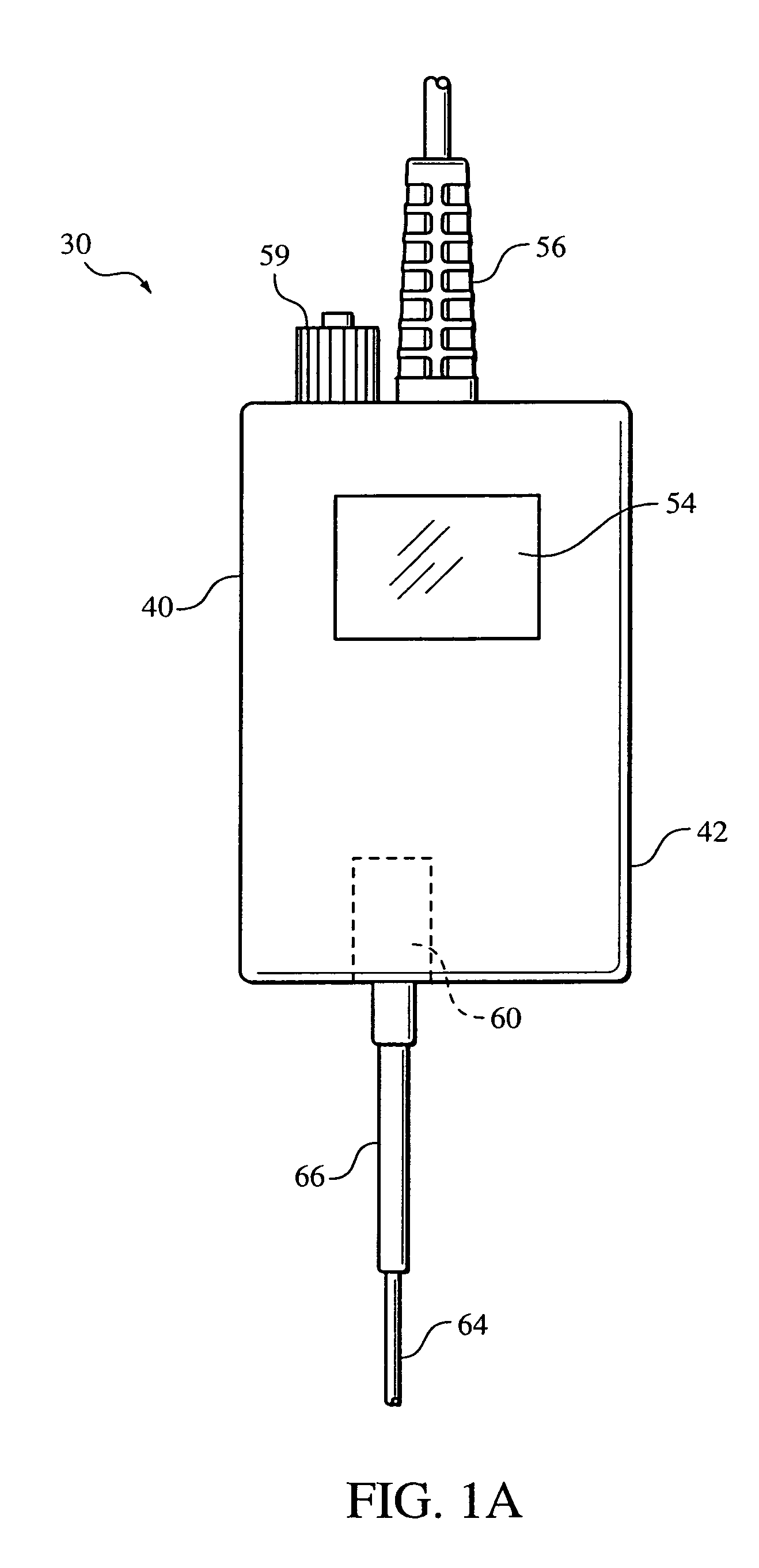
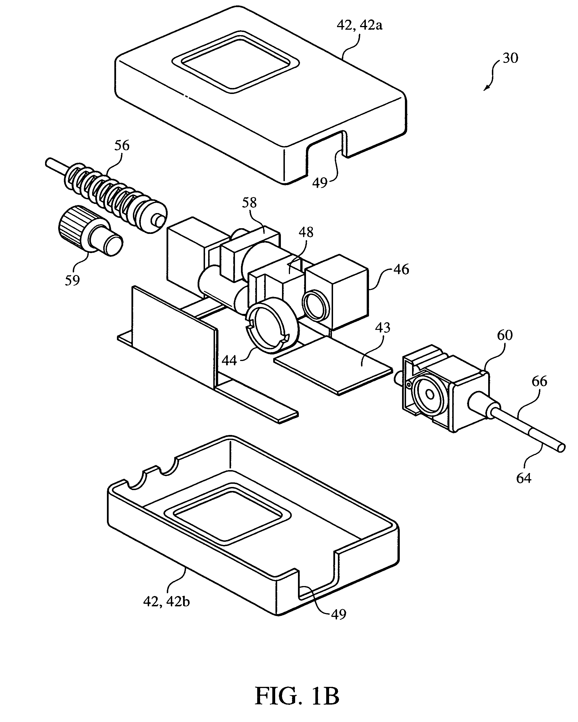
[0034]FIGS. 1A and 1B illustrate a stand-alone sidestream gas sampling system 30 according to the principles of the present invention. Sidestream gas sampling system 30 includes a sidestream gas measurement assembly 40 and a sample cell 60 that selectively attaches to the sidestream gas measurement assembly. Sidestream gas measurement assembly 40 is shown in exploded view in FIG. 1B.

[0035]Sidestream gas measurement assembly 40 includes a housing 42, which, in an exemplary embodiment of the present invention, is defined by two housing portions 42a and 42b that are adapted to be joined together in an assembled relation. The various elements of sidestream gas measurement assembly 40 may be at least partially contained within or otherwise carried by housing 42, which is configured to receive a substrate 43 on which one or more of the components of the sidestream gas measurement assembly can be mounted. A radiation source 44 and a radiation detector 46 are disposed in the housing in opti...

second embodiment

[0048]FIGS. 2A-2C illustrate a sidestream gas sampling system 80. In this embodiment, the sidestream gas sampling system, and, in particular, sidestream gas measurement assembly 82, is a component in a multiparameter monitoring apparatus 84. The components of sidestream gas measurement assembly 82 are generally the same as sidestream gas measurement assembly 40 of FIGS. 1A and 1B. For example, housing 86 of sidestream gas measurement assembly 82 housing contains a gas sensing system, including radiation source 44 and radiation detector 46 and includes a slot 49′ into which sample cell 60 is inserted for placing the window of the sample cell in optical alignment with the components of the gas sensing system. An aperture 88 is provided in housing 86 to for scavenging port 59.

[0049]As shown in FIG. 2C, sidestream gas sampling system 80 is one of a plurality of modules 90 in multi-parameter monitoring apparatus 84. Thus, sidestream gas measurement assembly 82 is preferably configured an...

third embodiment

[0050]FIGS. 3A-3C illustrate a sidestream gas measurement assembly 100 in a sidestream gas sampling system 102 that is adapted to be coupled to a multi-parameter monitoring system (not shown). Sidestream gas measurement assembly 100 includes a support bracket 104 and monitor connector 106 for coupling the sidestream gas measurement assembly to the remaining components of the multi-parameter monitoring system, which are not illustrated herein, such that the sidestream gas measurement assembly appears to be an integral part of the multi-parameter system, such as an extension of the housing for the multi-parameter system. The present invention contemplates securing support bracket 104 of sidestream gas measurement assembly 100 to the remaining components of the monitor by an adhesive layer 105 as well as connector 106. Sidestream gas measurement assembly 100 includes a housing 108 defined by a first housing portion 110 and a second housing portion 112 that are adapted to be joined toge...


PUM


Abstract

A sidestream sampling system includes a sidestream gas measurement assembly and a sample cell configured to be assembled therewith. The sidestream gas measurement assembly includes a receptacle for removably receiving at least a portion of the sample cell. The sample cell is coupled to a sampling tube that is configured to communicate with an airway of an individual. When the sample cell is assembled with the sidestream gas measurement assembly, a window of the sample cell is oriented toward a corresponding source and / or detector of the sidestream gas measurement assembly to facilitate monitoring of an amount of at least one gas or vaporized material in an individual's respiration.

Description

CROSS-REFERENCE TO RELATED APPLICATIONS[0001]This application claims priority under 35 U.S.C. § 119(e) from provisional U.S. patent application Ser. No. 60 / 370,002 filed Apr. 4, 2002.BACKGROUND OF THE INVENTION[0002]1. Field of the Invention[0003]The present invention relates to a detachable sample cell for a sidestream respiratory gas sampling system, and, in particular, to a detachable sample cell that is readily removable from and replaceable in a sidestream respiratory gas sampling system.[0004]2. Description of the Related Art[0005]It is well-known by those skilled in the art that gas analyzers for the non-dispersive infrared (NDIR) type operate on the principle that the concentration of specific gases can be determined by (a) directing infrared radiation through a gas sample, (b) filtering this infrared radiation to minimize the energy outside the band absorbed by a specific gas in the gas sample, (c) measuring the radiation impinging upon a detecting device after having passe...

Claims


Application Information

Patent Timeline
IPC IPC(8): A61B5/08G01N33/497A61B5/083A61B5/097G01N1/02G01N21/03G01N21/35G01N21/61
CPCA61B5/0833A61B5/097
Inventor RICH, DAVID RPIERRY, ANTHONY TFUDGE, BRIAN MSANDOR, JOHN LTRIUNFO, JR., JOHN A
Owner RIC INVESTMENTS LLC
Learn More