
Method of managing the cleaning of heat transfer elements of a boiler within a furnace

a technology of heat transfer elements and cleaning methods, which is applied in the field of boilers, can solve the problems of inefficiency in the use of heat transfer elements, inability to clean the heating element, and inability to remove ash,

Active Publication Date: 2008-03-11
INT PAPER CO
View PDF10 Cites 17 Cited by
  • Summary
  • Abstract
  • Description
  • Claims
  • Application Information

AI Technical Summary

Benefits of technology

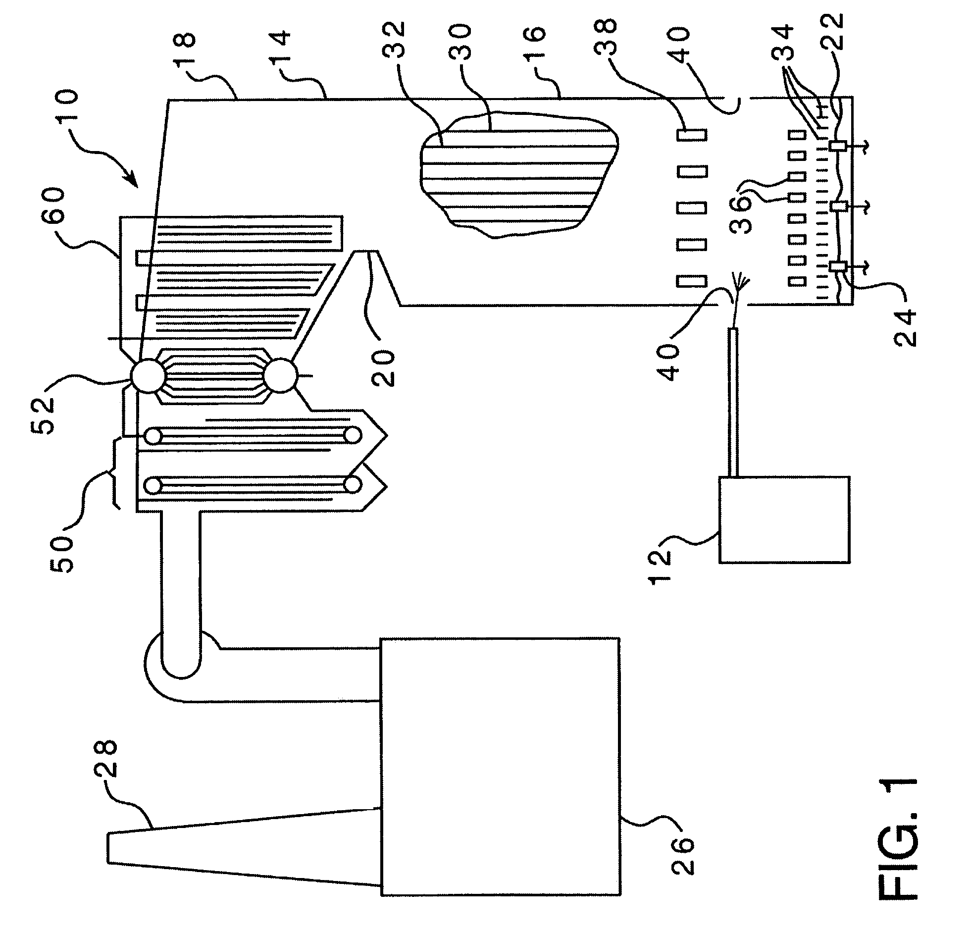
The present invention provides a method for cleaning the heat transfer surfaces of a heat transfer element in a furnace superheater when the heat transfer surfaces become fouled with ash. The method involves measuring the weight of ash on the support structure using a weighing system and using a cleaning system to remove the ash. The cleaning system includes multiple cleaning elements that operate at different efficiency rates. The method also includes managing the cleaning elements based on their efficiency rates to promote efficient cleaning. The invention helps to prolong the life of the heat transfer elements and improve the overall performance of the furnace.

Problems solved by technology

While the furnace is in use, the heat transfer elements will become fouled with ash.
Each heat transfer element can support a maximum amount of ash before the use of the heat transfer element becomes inefficient.
If this quantity of ash is not removed, the cost of operating the cleaning element is not justified by the amount of ash being removed.
That is, if it is determined that a specific cleaning element is not removing a sufficient quantity of ash, that cleaning element may have additional steam delivered thereto, have an additional cleaning stroke performed or be disabled.
That is, for example, if two cleaning elements are cleaning a single heat transfer element, and it is determined that one of the cleaning elements is performing more efficiently that the other, the less efficient cleaning element may be disabled.
When one of the cleaning elements fall below the minimum efficiency rate, only the use of that cleaning element is disabled.

Method used


Image

  • Method of managing the cleaning of heat transfer elements of a boiler within a furnace
  • Method of managing the cleaning of heat transfer elements of a boiler within a furnace
  • Method of managing the cleaning of heat transfer elements of a boiler within a furnace

Examples


Embodiment Construction

[0031]As used herein, the word “disabled” when used to describe a steam sootblower shall indicate that the supply of steam to that sootblower has been turned off, or reduced significantly.

[0032]As used herein, the word “manage” when applied to the cleaning system, a cleaning element, or cleaning elements shall mean the selective use / activation of a cleaning element or elements. Further, when applied to a steam sootblower, the word “manage” shall mean the selective supply of the amount of steam to a steam sootblower.

[0033]As used herein, the word “supplied” when applied to an efficiency rate shall mean that the efficiency rate is based on design factors known about the cleaning elements or cleaning system.

[0034]As used herein, the word “determining” when applied to an efficiency rate shall mean that the efficiency rate is based on data collected during the use of the cleaning elements or cleaning system.

[0035]As used herein, the word “provided” when applied to an efficiency rate shal...


PUM


Abstract

A method of cleaning a heat transfer element within a boiler furnace is provided. The method includes the steps of allowing a furnace to operate and deposit ash on a heat transfer element, determining an efficiency rate for at least one cleaning element, and managing the cleaning element based on the efficiency rate.

Description

BACKGROUND OF THE INVENTION[0001]1. Field of the Invention[0002]The present invention relates to boilers and, in particular, to a method and apparatus for measuring the effectiveness of sootblowers that remove ash deposits on the superheaters of the boilers used with the kraft pulping process.[0003]2. Background Information[0004]In the paper-making process, chemical pulping yields, as a by-product, black liquor, which contains almost all of the inorganic cooking chemicals along with the lignin and other organic matter separated from the wood during pulping in a digester. The black liquor is burned in a boiler. The two main functions of the boiler are to recover the inorganic cooking chemicals used in the pulping process and to make use of the chemical energy in the organic portion of the black liquor to generate steam for a paper mill. The twin objectives of recovering both chemicals and energy make boiler design and operation very complex. As used herein, a “boiler” indicates a top...

Claims


Application Information

Patent Timeline
Patent Type & Authority Patents(United States)
IPC IPC(8): B08B3/00B08B9/00
CPCF22B37/48F22B37/56F28G1/166F28G15/00F28G15/003
Inventor JONES, ANDREWCARLIER, TIM
Owner INT PAPER CO
Learn More