
Wireless network infrastructure including wireless discovery and communication mechanism

a wireless discovery and communication mechanism technology, applied in the field of wireless computer networks, can solve the problems of uncoordinated handoffs of wireless clients, difficult management of a large number of access points, and many problems affecting network management, mobility, performance,

Active Publication Date: 2008-03-04
CISCO TECH INC
View PDF15 Cites 73 Cited by
  • Summary
  • Abstract
  • Description
  • Claims
  • Application Information

AI Technical Summary

Benefits of technology

This approach enables efficient management and configuration of access points, reduces latency, and improves network performance by allowing access elements to discover and communicate with each other over the air, coordinating tasks such as hand-offs and channel assignments.

Problems solved by technology

This results in uncoordinated handoffs of wireless clients moving between access points.
An uncoordinated system of access points makes it difficult to manage a large number of access points, because there is no point of coordination.
This type of distributed architecture creates many problems affecting network management, mobility, and performance.
Since the access points act in their own self-interest and are not aware of the actions taken by surrounding access points, they handle mobility (e.g., handoff actions) as a local event, which significantly increases latency.
Configuration and management of wireless network systems incorporating many managed access points can be complicated and time consuming.
For example, configuration of the access elements and / or central control elements in the hierarchical wireless network architecture disclosed above can be complicated and / or time consuming, especially where large number of access elements and central control elements are deployed.
However, many discovery mechanisms do not work across Local Area Networks or different LAN segments without being configured with higher-layer addresses.
This can be problematic to the coordinated operation of two neighboring access elements connected to two different LAN segments.

Method used


Image

  • Wireless network infrastructure including wireless discovery and communication mechanism
  • Wireless network infrastructure including wireless discovery and communication mechanism
  • Wireless network infrastructure including wireless discovery and communication mechanism

Examples


Embodiment Construction

)

[0015]For didactic purposes an embodiment of the present invention is described as operating in a WLAN environment as disclosed in U.S. application Ser. Nos. 10 / 155,938 and 10 / 407,357 incorporated by reference herein. As discussed below, however, the present invention can be implemented according to a vast array of embodiments, and can be applied to a variety of WLAN architectures.

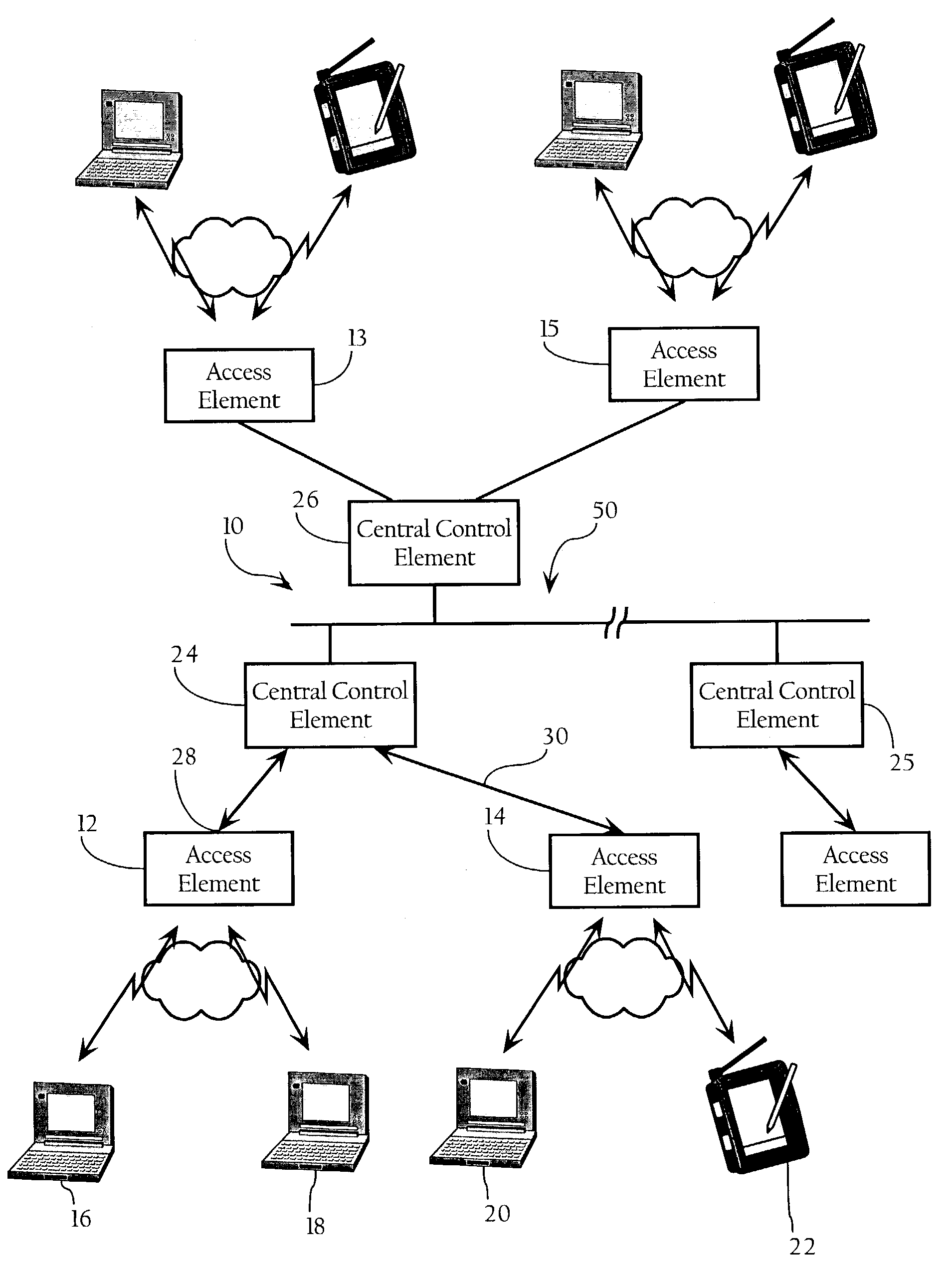
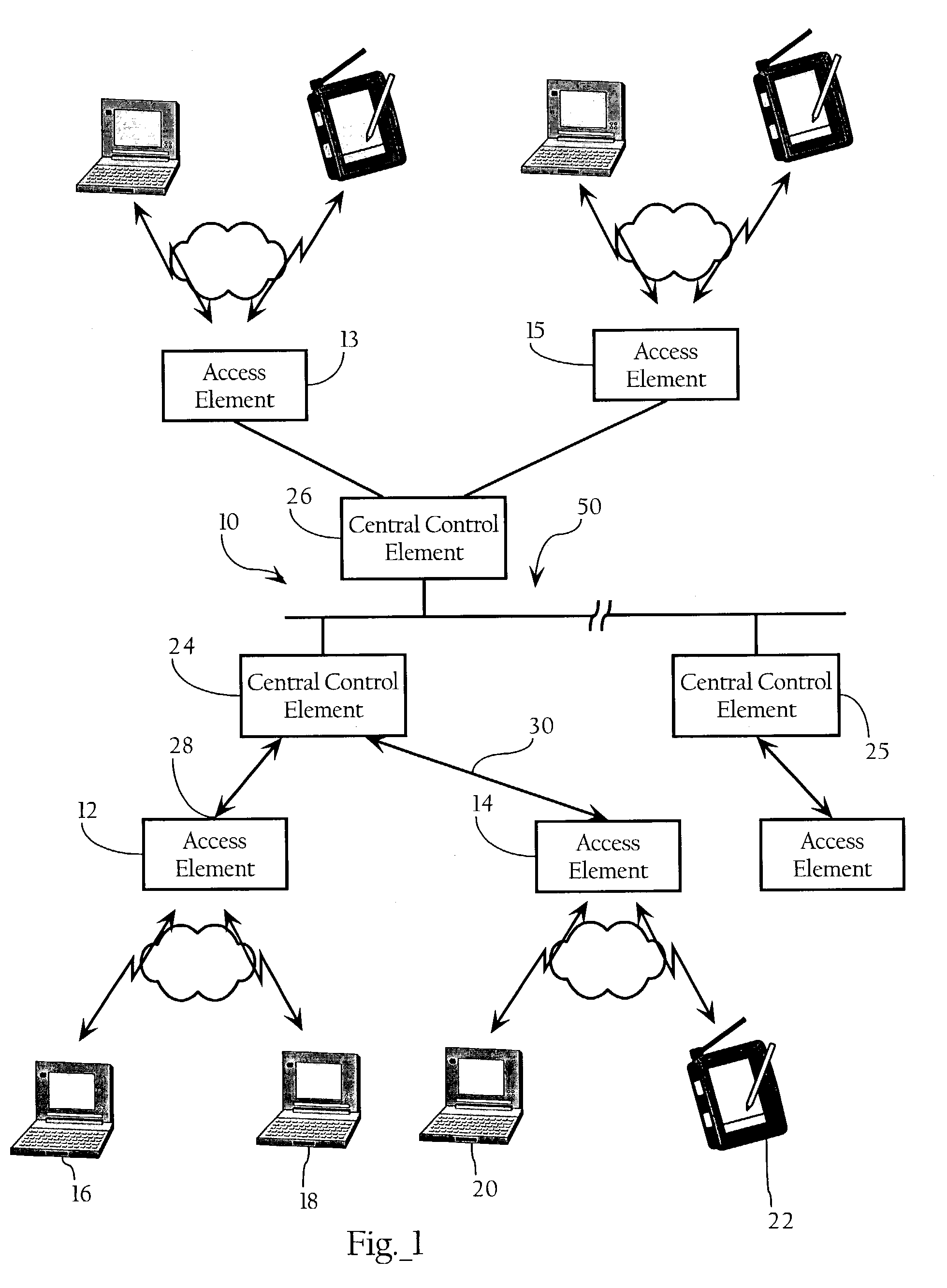
[0016]FIG. 1 illustrates a wireless computer network environment according to an embodiment of the present invention. Referring to FIG. 1, there is shown a block diagram of a wireless Local Area Network system 10 according to an embodiment of the invention. A specific embodiment of the invention includes the following elements: access elements 12, 14 for wireless communication with selected client remote elements 16, 18, 20, 22 central control elements 24, 25, 26, and means for communication between the access elements and the central control elements, typically direct line access 28, 30, but potentially ...


PUM


Abstract

A wireless discovery and communication mechanism to facilitate configuration, management and performance tasks associated with wireless network environments. In certain embodiments, access elements transmit and receive neighbor messages on a periodic basis to neighboring access elements. The neighbor messages can include configuration and / or protocol information to allow the access elements or associated devices to discover each other over the air. The present invention can be applied to a variety of wireless network architectures, such as a plurality of distributed, substantially autonomous access points, or to a hierarchical wireless network system comprising central control elements, each supervising and controlling one or more access elements as described more fully below.

Description

CROSS-REFERENCE TO RELATED APPLICATIONS[0001]This application makes reference to the following commonly owned U.S. patent applications and / or patents, which are incorporated herein by reference in their entirety for all purposes:[0002]U.S. patent application Ser. No. 10 / 155,938 in the name of Patrice R. Calhoun, Robert B. O'Hara, Jr. and Robert J. Friday, entitled “Method and System for Hierarchical Processing of Protocol Information in a Wireless LAN,” and[0003]U.S. patent application Ser. No. 10 / 407,357 in the name of Patrice R. Calhoun, Robert B. O'Hara, Jr. and Robert J. Friday, entitled “Method and System for Hierarchical Processing of Protocol Information in a Wireless LAN.”FIELD OF THE INVENTION[0004]The present invention relates to wireless computer networks and, more particularly, to methods, apparatuses and systems implementing wireless discovery and communication mechanisms to facilitate configuration, management and performance tasks associated with wireless network envi...

Claims


Application Information

Patent Timeline
Patent Type & Authority Patents(United States)
IPC IPC(8): H04M3/00
CPCH04W40/246H04W84/12
Inventor O'HARA, JR., ROBERT B.FRIDAY, ROBERT J.CALHOUN, PATRICE R.DIETRICH, PAUL F.
Owner CISCO TECH INC
Learn More