
Time-frequency domain reflectometry apparatus and method

a reflectometry and time-frequency domain technology, applied in the field of time-frequency domain reflectometry apparatus and method, can solve the problems of limited detection and localization accuracy, serious damage to the overall system, wiring problems,

Inactive Publication Date: 2008-02-26
IND ACADEMIC CORP FOUND YONSEI UNIV
View PDF11 Cites 77 Cited by
  • Summary
  • Abstract
  • Description
  • Claims
  • Application Information

AI Technical Summary

Benefits of technology

The present invention provides a time-frequency domain reflectometry apparatus for detection and localization of faults in a conductor. The apparatus can architect an input signal in time-frequency domain fitting to frequency characteristics of a conductor under test. The apparatus uses a chirp signal and a Gaussian envelope in the time domain as the reference signal. The apparatus can capture the advantages of both TDR and FDR and provide flexible application depending on the physical characteristics of the wire or cable under test. The apparatus can be used in various applications such as geographic / resource surveys, material surface tests, radar / sonar purposes, communication network wirings, optical cable diagnoses, remote explorations, fluid pipe leakage detections, water gauges, etc.

Problems solved by technology

A tiny fault on a wire might cause arcing, which may result in serious damages to the overall system.
This problem is not limited to commercial aircraft only systems where complicated wiring is involved and higher safely is required, like military aircraft, space shuttle, nuclear power plants and very tall buildings, etc., might face wiring problems.
However, technical problems with these methodologies are the fact that their resolution and accuracy performance for detection and localization are limited, because both time domain reflectometry and frequency domain reflectometry rely on the analysis of the reflected signals in only one domain, either time or frequency.
A drawback of this method is that its resolution is limited by rise time of the pulse wave.
Since the energy of the impulse is spread over a broad frequency range, TDR is usually not suitable for investigating the RF properties of a cable, which is important, for example, when dealing with wires / cables used for communication purposes.
The FDR, being a method for analyzing signals in frequency domain alone, is limited in its resolution by sweep bandwidth.
Furthermore, it has a drawback that its accuracy in distance estimation of faults is lowered in the presence of noise as in case of the TDP.

Method used


Image

  • Time-frequency domain reflectometry apparatus and method
  • Time-frequency domain reflectometry apparatus and method
  • Time-frequency domain reflectometry apparatus and method

Examples


Embodiment Construction

[0034]Now, construction of the present invention is explained below in more detail by describing the implementation of the invention with the accompanying drawings.

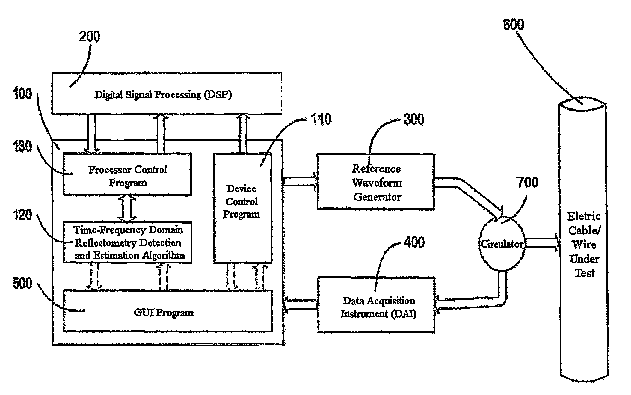
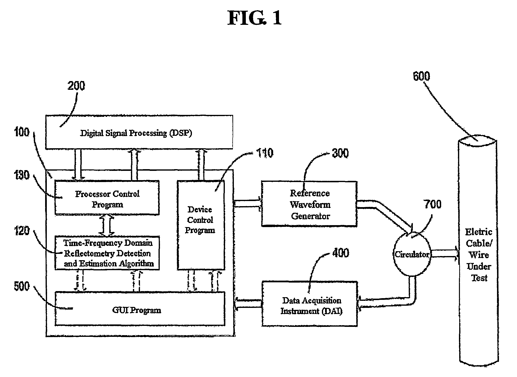
[0035]FIG. 1 is a block diagram showing control process in a time-frequency domain reflectometry apparatus in accordance with the present invention.

[0036]As shown above, Numeral 100, which represents a personal computer (PC), is a device where the main program of a time-frequency domain reflectometry apparatus in accordance with the present invention is executed.

[0037]Numeral 200, representing a DSP, computes time-frequency distribution functions.

[0038]Numeral 300, representing an AWC; generates input reference signals for a wire / conductor under test.

[0039]Numeral 400, representing a DAI, acquires reflected signal from a wire / conductor under test as well as input signal generated by an AWG via a circulator, and stores the same.

[0040]For the execution of the detection and localization, the above AWG 300 generates input ref...


PUM

PropertyMeasurementUnit
time-aaaaaaaaaa
frequencyaaaaaaaaaa
time delayaaaaaaaaaa

Abstract

An apparatus and method for high-resolution reflectometry that operates simultaneously in both the time and frequency domains, utilizing time-frequency signal analysis and a chirp signal multiplied by a Gaussian time envelope. The Gaussian envelope provides time localization, while the chirp allows one to excite the system under test with a swept sinewave covering a frequency band of interest. High resolution in detection of the reflected signal is provided by a time-frequency cross correlation function. The high-accuracy localization of faults in a wire / cable can be achieved by measurement of time delay offset obtained from the frequency offset of the reflected signal. The apparatus enables one to execute an automated diagnostic procedure of a wire / cable under test by control of peripheral devices.

Description

TECHNICAL FIELD OF THE INVENTION[0001]The present invention is a new apparatus and methodology in instrumentation and measurement for detection and localization of the faults in a wire or cable of an electric or electronic system where high level of reliability is required. In particular, the invented apparatus is capable of detection and localization of faults in high resolution based on the time-frequency domain reflectometry methodology that allows one to consider time and frequency simultaneously while the conventional apparatus and methods rely on either time or frequency only. Therefore, the invented apparatus and method achieve higher accuracy in detection and localization of faults in variety types of cable and wire.THE STATE OF THE ART[0002]The importance of electrical wiring and associated faults has been highlighted by the investigation of several aircraft crashes. A tiny fault on a wire might cause arcing, which may result in serious damages to the overall system. This p...

Claims


Application Information

Patent Timeline
Patent Type & Authority Patents(United States)
IPC IPC(8): G01R31/08G01R31/02G01R27/04G01R31/11H01B13/00H02G1/06
CPCG01R31/088G01R31/11G01R31/08
Inventor PARK, JIN-BAESHIN, YONG-JUNEYOOK, JONG-GWANPOWERS, EDWARD J.SONG, EUN-SEOKKIM, JOO-WONCHOE, TOK-SONSUNG, SEUNG-HOON
Owner IND ACADEMIC CORP FOUND YONSEI UNIV
Learn More