
Concrete slab joint stabilizing system and apparatus

a concrete slab and joint stabilizing technology, applied in bridges, bridge structural details, roads, etc., can solve the problems of reducing the service life of concrete pavement, and affecting the stability of concrete pavement joints, etc., to achieve the effect of stabilizing loose floor or pavement joints and generating highly concentrated shear forces

Active Publication Date: 2008-02-26
ILLINOIS TOOL WORKS INC
View PDF8 Cites 12 Cited by
  • Summary
  • Abstract
  • Description
  • Claims
  • Application Information

AI Technical Summary

Benefits of technology

[0024]It is another object to provide a method and apparatus of the character described that provides for stabilizing of loose floor or pavement joints between adjacent concrete slab sections that, in use, are subjected to traffic thereupon.
[0025]It is another object to provide a method and apparatus of the character described for stabilizing loose floor or pavement joints between adjacent concrete slab sections in which the generation of highly concentrated shear forces upon adjacent concrete slab sections is minimized.
[0026]It is another object to provide a method and apparatus of the character described for stabilizing loose floor or pavement joints between adjacent concrete slab sections that requires only minimal, temporary, disruption of use by traffic thereupon.
[0027]It is another object to provide a method and apparatus of the character described for stabilizing loose floor or pavement joints between adjacent concrete slab sections that accommodates anticipated expansion and contraction of the concrete slab sections.
[0028]It is another object to provide a method and apparatus of the character described for stabilizing loose floor or pavement joints between adjacent concrete slab sections that requires minimal equipment or expertise to install.

Problems solved by technology

Since concrete has excellent compressive strength, the use of reinforcement steel bar in many on-grade slab applications has often been considered unnecessary.
Concrete pavement, including roads, highways, alleys, parking lots, loading docks, airport runways, taxiways, and aprons, is also subject to damage from the elements.
Damage caused by freezing rain to concrete slabs that are exposed to the weather is well known, as is damage to concrete slabs caused by thermal expansion and contraction of the concrete slab sections themselves.
However, application of joint filler, alone, is of virtually no use in preventing further damage to the slab in the vicinity of (sealed) cracks that may be caused by heavy loads imparted by vehicular traffic to the slab in the vicinity of the (sealed) cracks.
Nonetheless, indoor concrete flooring slabs are vulnerable to thermal expansion- and contraction-induced cracking.
However, as on-grade concrete slabs continue to cure, the edges (particularly the opposed edges of slab sections at loose joints) curl up.
Even when only subjected to substantially vertical compressive loads (for example, due to heavy vehicular traffic over the slab), this results in damage to the slab section edges, and often causes progressively worse fracturing of these areas.
In addition, curling (of the slab section edges) by itself can present a problem for certain types of vehicles that may travel over the slab.
This phenomenon causes a temporary bump in the flooring, which can result in damage to the forklift, mishandling of the forklift and / or accelerated deterioration of the flooring.
Use of large pneumatic tires on the wheels of most vehicles such as trucks, cars, and airplanes can, in some instances, mitigate the effects of this phenomenon, but it does not eliminate the effects, particularly if the floor or pavement is subjected to heavy traffic.
However, this prior method is quite ineffective in preventing deterioration of section edges of on-grade concrete slabs that is caused by loading (for example, by vehicular traffic) of the slab.
In practice, however, it is extremely difficult to fully fill the voids beneath the edges of the concrete slab sections, and it is virtually impossible to prevent the formation of additional sub-slab voids, which may be caused, for example, by ground settlement, water seeping between the concrete slab and grade, and continued (upward) curling of the concrete slab edge.
The fact that slab replacement is performed is indicative of the limited effectiveness of the known alternatives in the prior art for preventing and repairing deterioration of loose joints in large horizontal concrete slabs.
Replacement of the entire slab of concrete obviously causes great disruption of traffic and other use of the affected floor or pavement.
All of the aforementioned prior methods involve a considerable amount of work and disruption of use of the affected pavement / floor.
A critical problem with most prior methods is the inability to transfer loads across loose joints of adjacent sections of concrete pavement or flooring.
This is why prior methods of sealing joints or cracks, while somewhat effective against damage from freezing water, is wholly ineffective against deterioration caused by traffic upon the surface across loose joints.
This is also why prior full-depth partial slab replacement methods (without steel dowels) result in exacerbating the problem, by inherently doubling the number of joints that exist.
This results in highly concentrated shear forces in the concrete in the vicinity of the dowels, which often leads to fractures in the concrete and / or cement.

Method used


Image

  • Concrete slab joint stabilizing system and apparatus
  • Concrete slab joint stabilizing system and apparatus
  • Concrete slab joint stabilizing system and apparatus

Examples


Embodiment Construction

[0075]The present invention now will be described more fully hereinafter with reference to the accompanying drawings, in which preferred embodiments of the invention are shown. This invention may, however, be embodied in many different forms and should not be construed as limited to the embodiments set forth herein; rather, these embodiments are provided so that this disclosure will be thorough and complete, and will fully convey the scope of the invention to those skilled in the art. Like numbers in the drawings and the specification refer to like elements throughout.

[0076]As will be described more fully herein below, the present invention provides methods and apparatus for stabilizing a construction joint between two substantially horizontal, substantially planar members. For purpose of explanation, the preferred embodiment of the invention is herein described in applications for stabilizing adjacent sections of on-grade concrete slabs. In the exemplary application described and i...


PUM

PropertyMeasurementUnit
lengthaaaaaaaaaa
lengthaaaaaaaaaa
diameteraaaaaaaaaa

Abstract

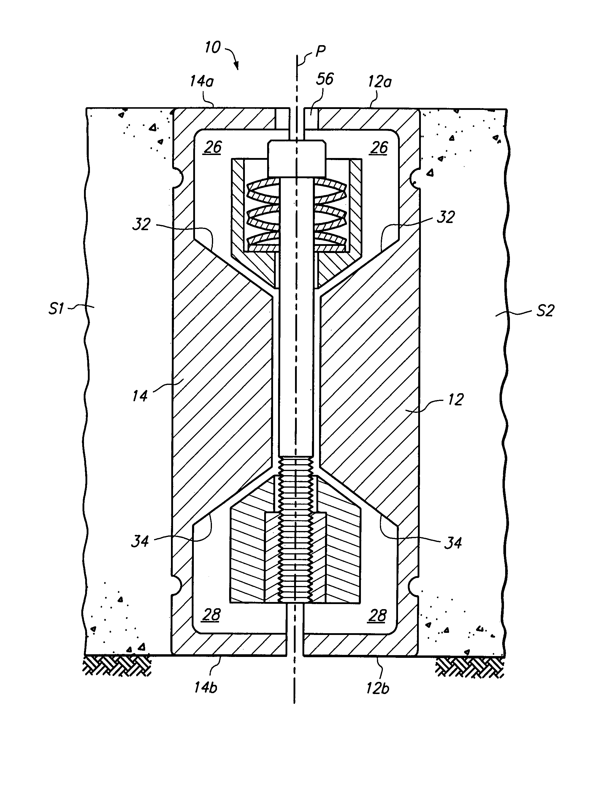
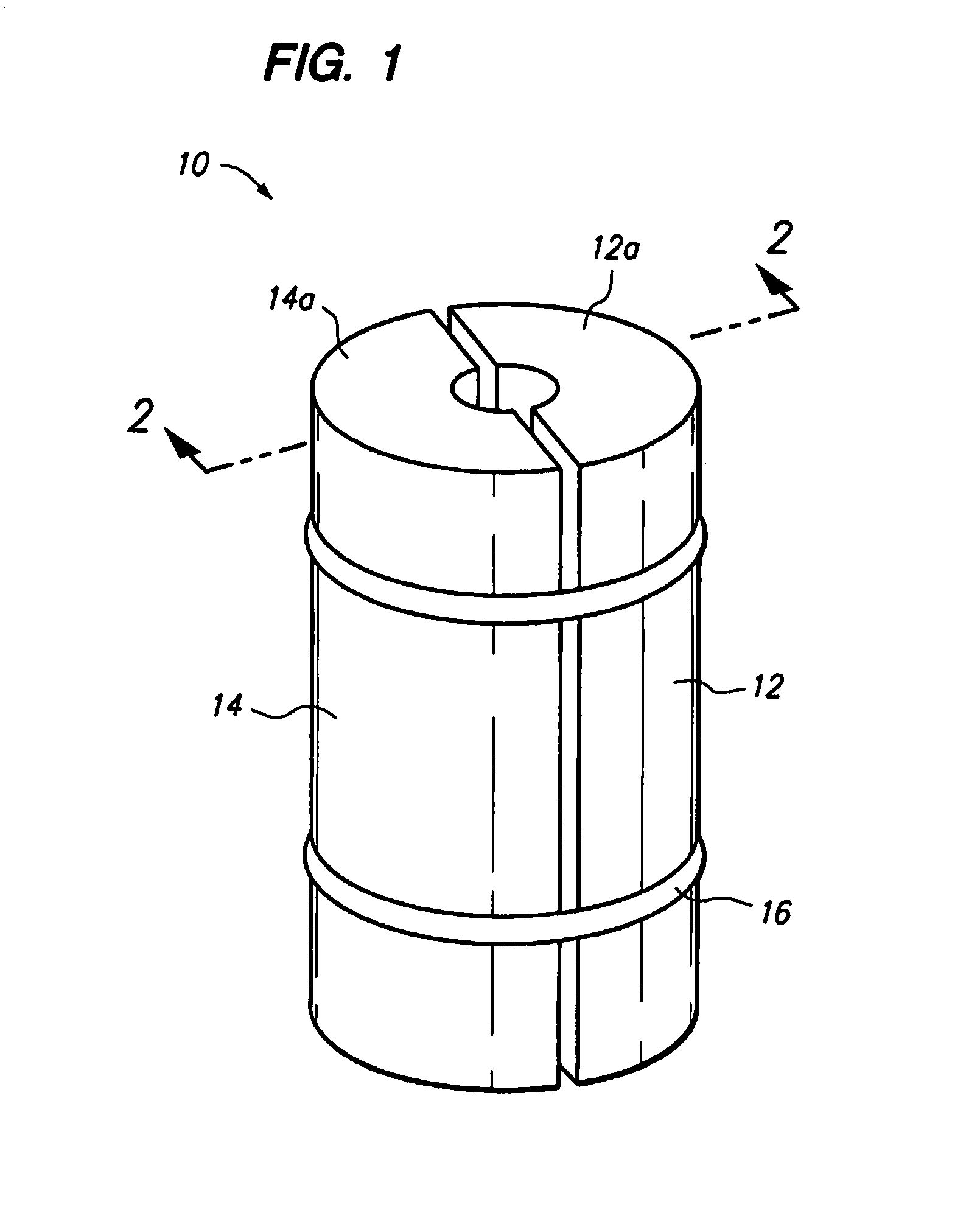
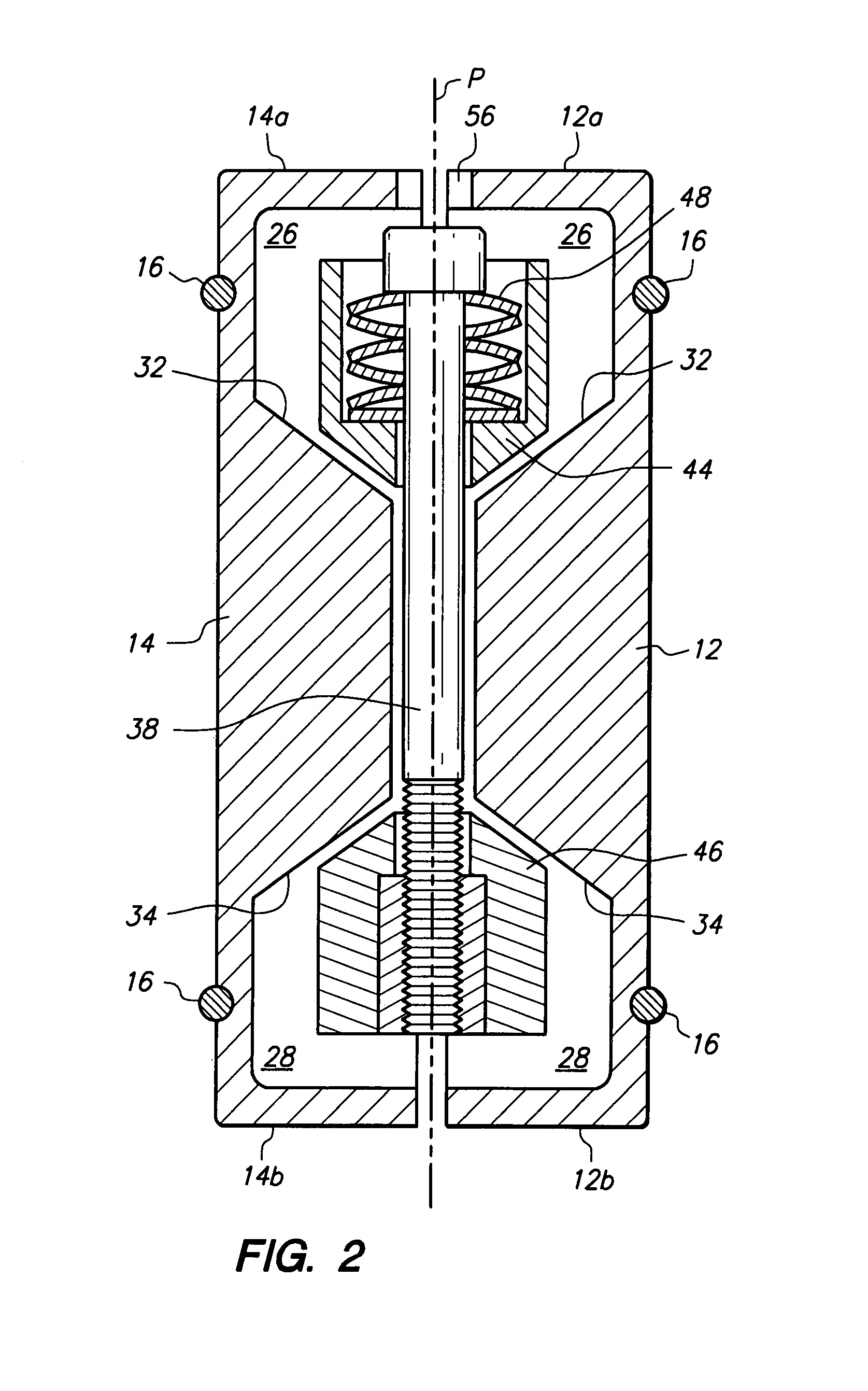
A joint stabilizing apparatus having an expandable cylindrical housing is inserted into a circular hole drilled at a “loose joint” of a concrete slab that is to be stabilized against relative vertical displacement between adjacent slab sections. The hole is drilled downward into the concrete, centered on the plane of a lateral opening / joint in the concrete slab. The expandable housing comprises two rigid semi-circular housing halves, and the assembly is oriented inside of the circular hole such that the two housing halves are on opposite sides of the centerline of the lateral opening / joint. The housing halves are pushed apart by turning of a threaded bolt inside of the housing. Turning of the bolt causes two bi-laterally symmetric wedge blocks to draw towards each other, and pressing the bearing surfaces of the wedge blocks against inclined surfaces inside of the respective housing halves. As the housing halves are pushed apart, the outside surfaces of the expandable housing engage the walls of the drilled hole and apply opposing horizontal compressive forces to the slab sections. Friction between the expandable housing and the concrete slab sections prevent the slab sections from vertically moving relative to each other.In other embodiments of the invention, the joint stabilizing apparatus is used to prevent relative motion between non-horizontal construction members, and between four adjacent slab sections separated by intersecting loose joints.

Description

CROSS-REFERENCE TO RELATED APPLICATION[0001]This application claims the benefit of provisional patent application No. 60 / 659,071 filed on Mar. 8, 2005.BACKGROUND OF THE INVENTION[0002]1. Field of the Invention[0003]The present invention relates to restoration of load transfer capacity in horizontal concrete slabs, particularly restoration of load transfer capacity in horizontal concrete slabs by retrofit mechanical reinforcement of control and other joints.[0004]2. Description of the Prior Art[0005]The pouring of large horizontal concrete slabs on top of “grade” or graded earth or gravel, without any reinforcement steel bar (or “rebar”), is a fairly common practice. This practice is used both for outside pavement and indoor flooring on which wheeled traffic is expected. The load imparted by wheeled traffic to “on-grade” concrete slabs is predominantly compressive. Since concrete has excellent compressive strength, the use of reinforcement steel bar in many on-grade slab applications...

Claims


Application Information

Patent Timeline
Patent Type & Authority Patents(United States)
IPC IPC(8): E01C11/10E01C11/14E01C11/16E01C11/02
CPCE01C7/147E01C11/14Y02A30/60
Inventor COSTA, ROBERT P.IM, DO SUN
Owner ILLINOIS TOOL WORKS INC
Learn More