Eureka AIR delivers breakthrough ideas for toughest innovation challenges, trusted by R&D personnel around the world.

A damper opening and closing angle changing mechanism of a hinge

A technology of angle change and damper, which is applied to hinges with pins, switches with braking devices, mechanical equipment, etc., can solve the problems of unsatisfactory use requirements, inability to achieve uniformity, high friction, etc., and improve the use of The effect of experience, wide range of use, and small collision

Active Publication Date: 2018-04-06
伍志勇
View PDF5 Cites 0 Cited by
  • Summary
  • Abstract
  • Description
  • Claims
  • Application Information

AI Technical Summary

Problems solved by technology

It is said that this structure can reduce noise, and the closing or opening movement of the cabinet door is more flexible. During the movement of the cabinet door, the overall translational movement can avoid the situation that ordinary cabinet doors may hit the head; however, the upper The flap hinges only use elastic components to achieve buffering and damping, and the force during the closing or opening movement cannot achieve a uniform effect, and the elastic component has a large friction force and high noise when the upper flap is hinged to open and close, which cannot meet the needs of users.

Method used


Image

  • A damper opening and closing angle changing mechanism of a hinge
  • A damper opening and closing angle changing mechanism of a hinge
  • A damper opening and closing angle changing mechanism of a hinge

Examples


no. 1 example

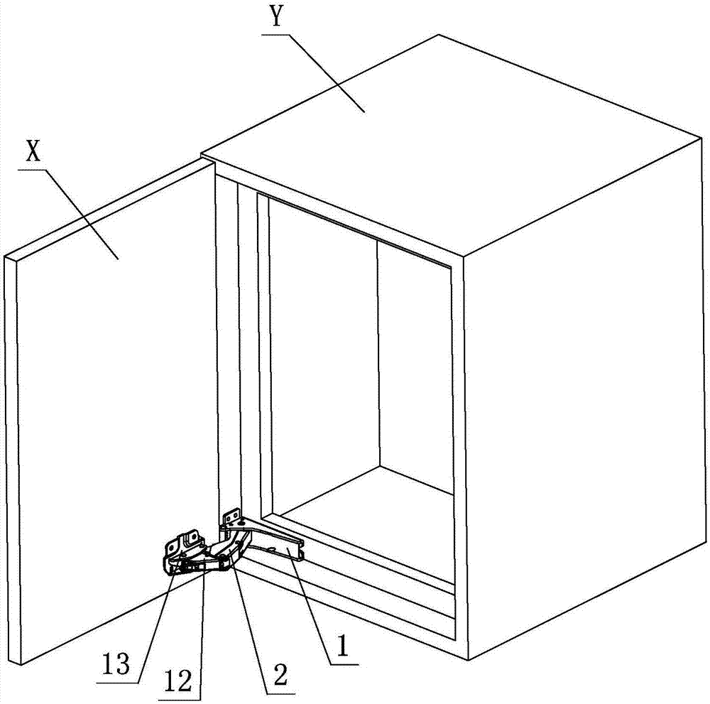
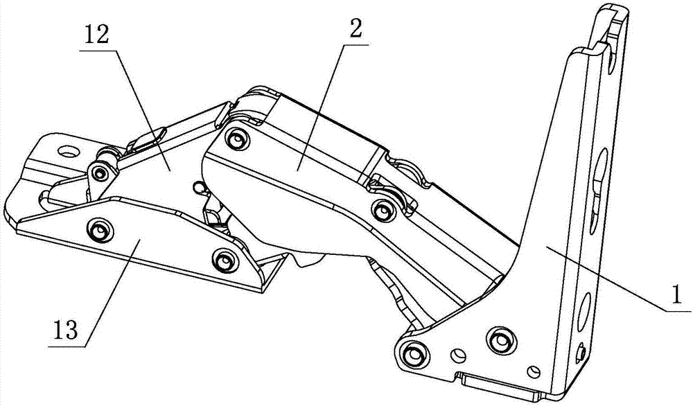
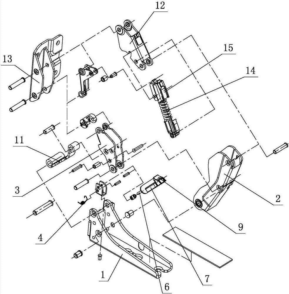
[0023] see Figure 1-Figure 7 The opening and closing angle change mechanism of the damper of this hinge includes a stop element 1, a connecting element 2 and a lever element 3 which are hingedly matched with each other, a damper is arranged between the stop element 1 and the connecting element 2, and one end of the damper is rotated to set On the blocking element 1, the other end rests on the connecting element 2, and the connecting element 2, the lever element 3 and the damper are interlocked with each other relative to the blocking element 1 when the hinge is opened and closed; at least when the hinge is closed at a certain angle, The lever element 3 acts on the damper and drives the damper to stop and slide on the connecting element 2, and the damper compresses and generates a damping force to realize damped closing of the hinge.

[0024] Furthermore, one end of the connecting element 2 is rotatably hinged on the blocking element 1, the other end is rotatably hinged on the...

no. 2 example

[0035] see Figure 8 , the damper opening and closing angle change mechanism of this hinge is different from the first embodiment in that: the connecting element 2 is provided with a sliding limiter 5, one end of the damper is rotated and set on the blocking element 1, and the other end is passed through The sliding limiting part 5 limits sliding and relies on the connecting element 2 .

[0036] Other unmentioned parts are the same as the first embodiment.


PUM


Abstract

A damper opening and closing angle varying mechanism of a hinge comprises a blocking element, a connection element and a lever element which are in hinge fit with one another. A damper is arranged between the blocking element and the connection element. One end of the damper is rotationally arranged on the blocking element, and the other end of the damper abuts against the connection element. The connection element, the lever element and the damper are linked with one other relative to the blocking element when the hinge is opened or closed. When the hinge is closed by at least one certain angle, the lever element acts on the damper and drives the damper to slide on the connection element in a limited mode, the damper is compressed and generates damping force, and thus, damped closing of the hinge is achieved. Through the structure improvement, the damper opening and closing angle varying mechanism of the hinge has the characteristics that the structure is simple and reasonable, safety and reliability are achieved, production and implementation are easy, adjustment is fast, operation is convenient, the service life is long, practicability is high, and the opening and closing process is labor-saving, smooth, small in collision and low in noise.

Description

technical field [0001] The invention relates to a hinge damper opening and closing angle changing mechanism. Background technique [0002] The Chinese patent document number is CN202039710U, which discloses a hinge on November 16, 2011. The curved end of the first rotating arm of this structure is rotatably connected to the base plate, and the curved end of the second rotating arm is rotatably connected to the base plate. The two ends of the above-mentioned connecting arms that can overlap with the respective straight ends of the first rotating arm and the second rotating arm at the same time are rotatably connected with the respective straight ends of the first rotating arm and the second rotating arm respectively, and the connecting arms are located at the first Between the rotating arm and the second rotating arm, the bent end of the first rotating arm is hinged with the free end of the movable rod of the gas rod, and the fixed rod of the gas rod can be movably connected ...

Claims


Application Information

Patent Timeline
Patent Type & Authority Patents(China)
IPC IPC(8): E05F3/20E05D3/06E05D5/02F16J10/02
CPCE05D3/06E05D5/02E05D5/0215E05F3/20E05Y2800/422E05Y2800/43E05Y2900/20E05Y2900/308F16J10/02
Inventor 伍志勇
Owner 伍志勇
Why Eureka
Eureka Blog
Learn More