
Mold locking mechanism of plastic injection molding machine

An injection molding machine and mold clamping technology, applied in the field of plastic injection molding machines, can solve the problems of large overall volume of the mold clamping mechanism, long length of the mold clamping mechanism, and large floor space, so as to achieve concentrated force on the mold and improve the qualification rate. , the effect of improving the stress condition

Active Publication Date: 2014-01-22
NINGBO SHUANGMA MASCH IND CO LTD
View PDF6 Cites 0 Cited by
  • Summary
  • Abstract
  • Description
  • Claims
  • Application Information

AI Technical Summary

Problems solved by technology

However, many of the current clamping mechanisms fix the oil cylinder on the outside of the base, resulting in a longer length of the entire clamping mechanism; some clamping mechanisms use two oil cylinders, which are respectively installed on both sides of the thrust seat. However, no matter which of the above structures, the overall volume of the clamping mechanism is relatively large, resulting in a large footprint

Method used


Image

  • Mold locking mechanism of plastic injection molding machine
  • Mold locking mechanism of plastic injection molding machine
  • Mold locking mechanism of plastic injection molding machine

Examples


Embodiment 1

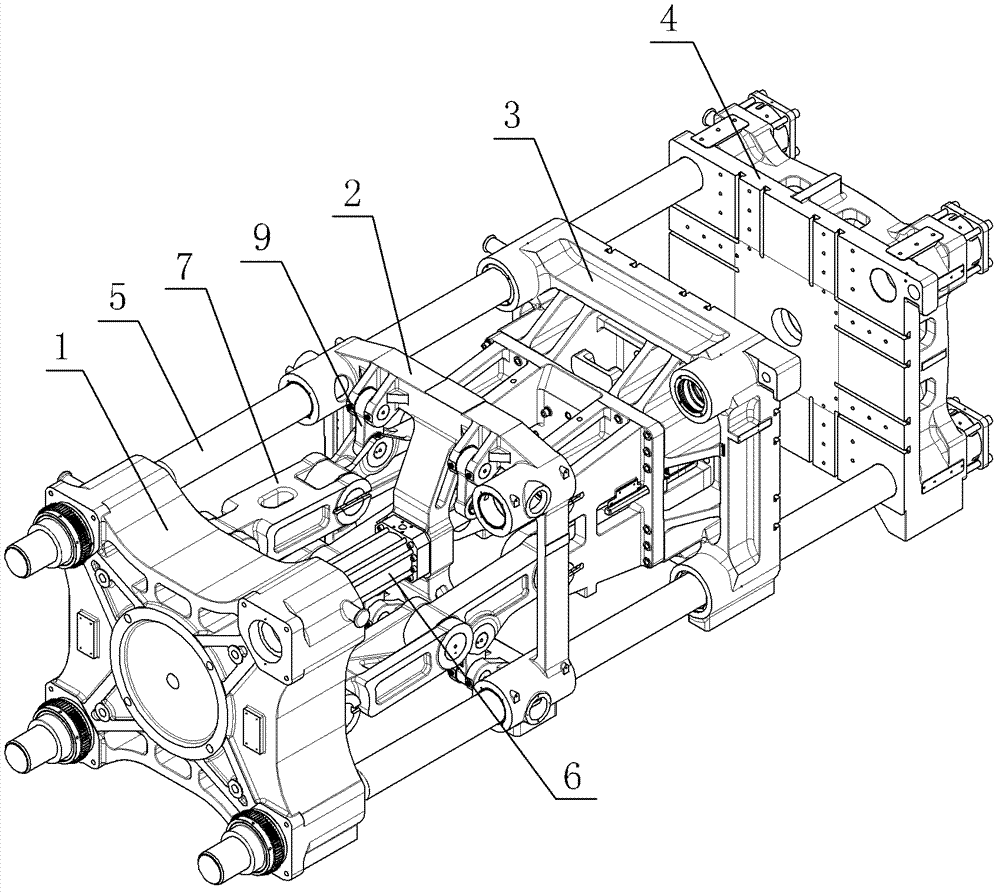
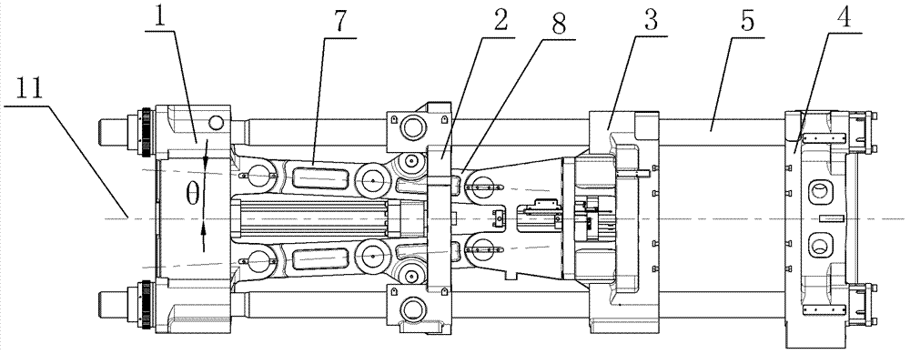
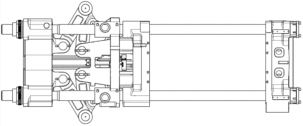
[0018] Embodiment 1: As shown in the figure, a mold clamping mechanism of a plastic injection molding machine includes a base 1, a thrust seat 2, a movable template 3 and a fixed template 4, which are arranged in sequence and whose centers are located on the same central axis 11, and the base 1 A guide rod 5 is fixedly arranged on the top, the thrust seat 2 and the movable formwork 3 are sleeved on the guide rod 5, the fixed formwork 4 is fixedly connected to the end of the guide rod 5, and the thrust seat 2 includes a frame formed by four connecting ribs 21. The outer frame, the corner of the outer frame is integrally provided with a guide seat 22, the guide seat 22 is sleeved on the guide rod 5, and a connecting rod 23 is integrally connected between a group of connecting ribs 21 arranged oppositely among the four connecting ribs 21. The rod 23 passes through the center of the thrust seat 2, and an oil cylinder 6 is fixedly installed on the connecting rod 23 at the center of ...

Embodiment 2

[0019] Embodiment 2: As shown in the figure, other mechanisms are the same as Embodiment 1. The difference is that among the four connecting ribs 21 of the thrust seat 2, two sets of connecting ribs 21 that are oppositely arranged are uniformly connected with connecting rods 23, two The intersecting portion of the connecting rods 23 is located at the center of the thrust seat 2 , and the oil cylinder 6 is fixedly installed at the intersecting portion of the two connecting rods 23 .

[0020] In the above-mentioned embodiment, the included angle θ can be selected according to actual design needs in the range of greater than 0° and less than or equal to 10°; When the connecting rod 23 is connected, two oil cylinders 6 that are symmetrical along the central axis 11 can be fixedly installed on the connecting rod 23, or three oil cylinders 6 can be fixedly installed on the connecting rod 23, and one of the oil cylinders 6 is located on the connecting rod 23. At the center of the thr...


PUM


Abstract

The invention discloses a mold locking mechanism of a plastic injection molding machine, comprising a base, a thrust seat, a moving mold plate and a fixed mold plate which are arranged in sequence, wherein the centers of the base, the thrust seat, the moving mold plate and the fixed mold plate are positioned on the same central axis; a guide rod is fixedly arranged on the base; the thrust seat and the moving mold plate are sheathed on the guide rod; the fixed mold plate is fixedly connected with the end part of the guide rod; and a connecting rod group is arranged between the moving mold plate and the base. The mold locking mechanism is characterized in that the thrust seat is internally and fixedly provided with at least one oil cylinder; and a piston rod of the oil cylinder is fixedly connected with the moving mold plate. The mold locking mechanism has the advantages that the length of the whole mold locking mechanism is reduced, the structure of the whole mechanism becomes compact, and the whole volume is reduced; and when the moving mold plate and the fixed mold plate are positioned in a locking state, the included angle of the center connecting line of a first connecting rod and a second connecting rod and the horizontal surface of the central axis is more than 0 degree but less than or equal to 10 degrees. In the structure, the acting force of the mold locking mechanism on the mold tends to the center of the mold, the stressing of the mold is more concentrated, and the qualification rate of plastic products is effectively improved.

Description

technical field [0001] The invention relates to a plastic injection molding machine, in particular to a mold locking mechanism of the plastic injection molding machine. Background technique [0002] Plastic products currently on the market are basically injection molded by injection molding machines. During the operation of the injection molding machine, due to the high pressure when the plastic is injected into the mold, the mold may be opened, so the injection molding machine is equipped with a mold locking mechanism. [0003] The clamping mechanism is basically composed of base, fixed template, movable template, thrust seat, oil cylinder and connecting rod assembly and other components. However, many of the current clamping mechanisms fix the oil cylinder on the outside of the base, resulting in a longer length of the entire clamping mechanism; some clamping mechanisms use two oil cylinders, which are respectively installed on both sides of the thrust seat. However, n...

Claims


Application Information

Patent Timeline
Patent Type & Authority Patents(China)
IPC IPC(8): B29C45/68
Inventor 刘玉鹏胡宝全喻鹏邓俊钧康晓军李向明
Owner NINGBO SHUANGMA MASCH IND CO LTD
Learn More