
Heat exchanger

a heat exchanger and heat exchange surface technology, applied in indirect heat exchangers, lighting and heating apparatus, transportation and packaging, etc., can solve the problems of reducing the air exiting temperature, cyclical fouling of heat exchanger surfaces in carbon black processes, and affecting the efficiency of heat exchangers, so as to reduce or minimize fouling of heat exchange surfaces in combustion air heat exchangers, inhibit the effect of fouling of heat exchange surfaces

Inactive Publication Date: 2008-02-12
CABOT CORP
View PDF38 Cites 2 Cited by
  • Summary
  • Abstract
  • Description
  • Claims
  • Application Information

AI Technical Summary

Benefits of technology

[0016]We have discovered that the fouling of a heat exchange surface in a heat exchanger may be reduced or minimized by maintaining a temperature difference between the heat exchange surface and a fluid stream in contact with the heat exchange surface. For example, fouling of the heat exchange surfaces in a combustion air heat exchanger may be reduced or minimized by maintaining the temperature difference between the heat exchange surface and the carbon black stream in contact with the heat exchange surface such that the temperature difference is sufficient to inhibit fouling of the heat exchange surface. In the case of a combustion air heat exchanger, the temperature difference between the heat exchange surface and the carbon black stream is preferably not greater than 500° F., more preferably not greater than 300° F. and even more preferably not greater than 100° F. Preferably the temperature difference is maintained throughout the heat exchanger. Depending on the carbon black production process, it is possible that at a particular temperature difference, fouling of the heat exchange surface may be substantially eliminated.
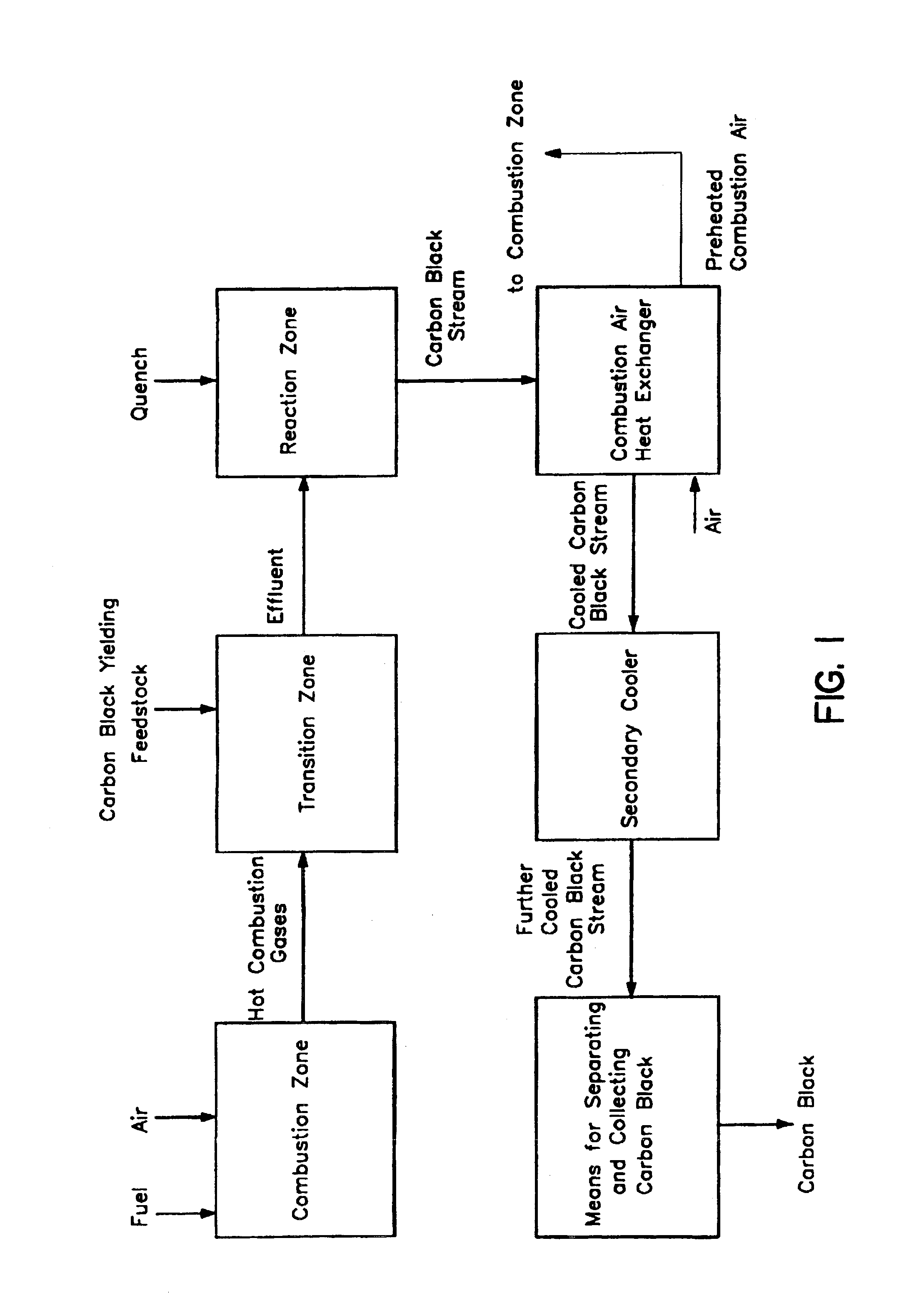
[0033]further cooling the carbon black stream in a secondary cooler to a temperature that prevents damage to the means utilized for separating and collecting the carbon black product; and separating and collecting carbon black product, wherein the temperature difference between the heat exchange surface and the carbon black stream is not greater than 500° F., more preferably not greater than 300° F. and even more preferably not greater than 100° F.
[0034]An advantage of the method and the heat exchanger of the present invention is that the heat exchange surface is less prone to fouling than conventional heat exchangers.
[0035]An advantage of the combustion air heat exchanger of the present invention is that the combustion air heat exchanger resists fouling of the heat exchange surface thereby minimizing the occurrence of the problems described above which beset conventional combustion air heat exchangers.
[0036]An advantage of the process for producing carbon blacks of the present invention is that the process produces a high purity carbon black product with substantially consistent morphology.

Problems solved by technology

A disadvantage with many heat exchangers utilized in carbon black production processes is that the combustion air heat exchangers operate in a fouled condition.
The fouling of heat exchanger surfaces in a carbon black processes is often cyclical in nature.
The fouling of heat exchanger surfaces in a carbon black production process can lead to a number of problems including:
less effective heat transfer resulting in lower air exiting temperatures (lower air preheat) and thus lower carbon black yields and production rates;
less effective heat transfer necessitating higher carbon black stream entering temperatures in order to achieve a desired air exiting temperature, thus increasing the stresses imposed on the heat exchanger materials;
less effective heat transfer resulting in variations in air exiting temperatures which result in variations in carbon black morphology.
an increase in heat exchanger pressure drop, which can result in lower production rates and greater stresses in the heat exchanger materials;
possible equipment damage;
and the tendency of the deposits to harden over time while on the heat exchange surface resulting in the possibility that the hardened deposits will re-enter the carbon black stream contaminating the carbon black product.

Method used


Image

  • Heat exchanger
  • Heat exchanger
  • Heat exchanger

Examples


example

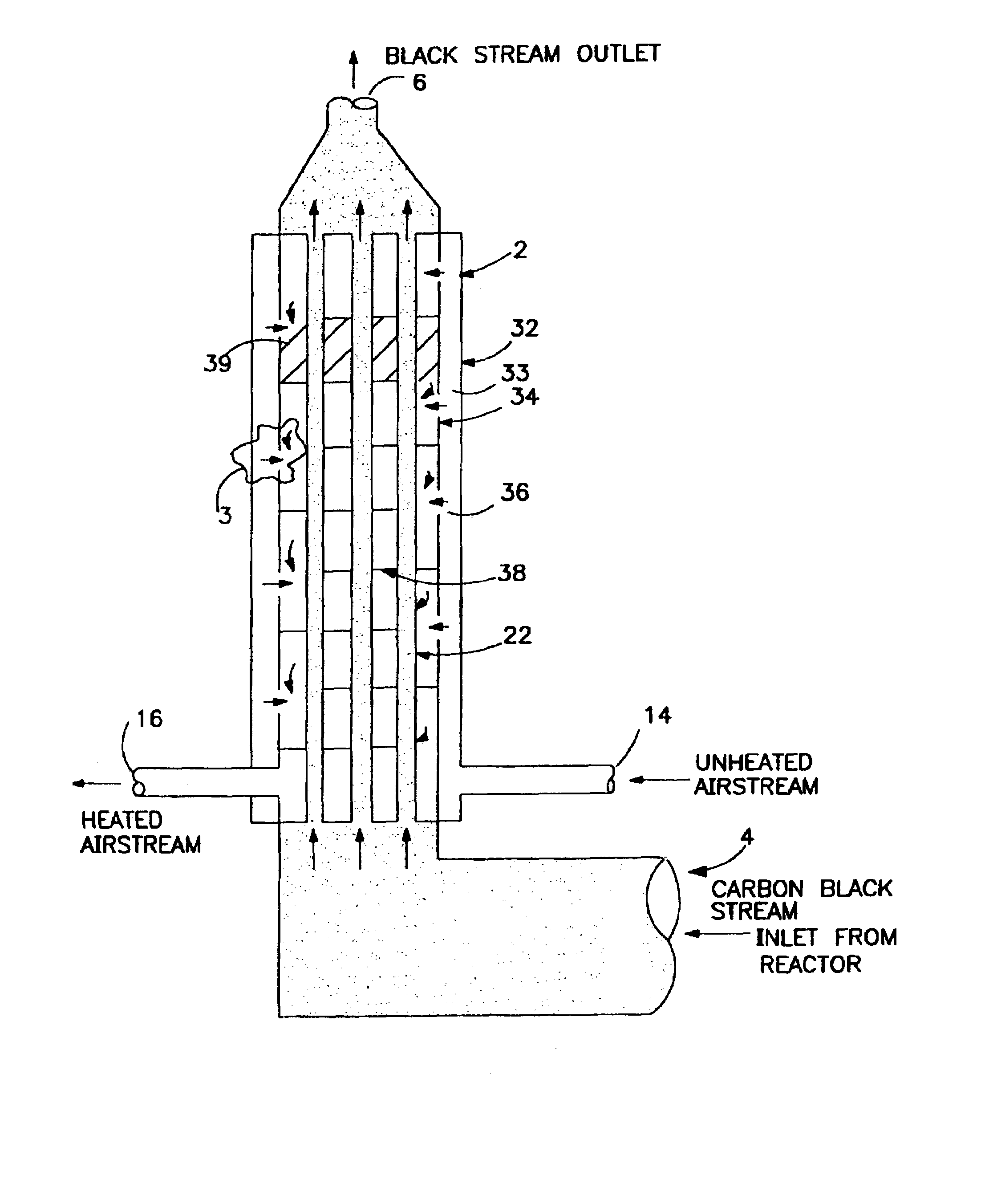
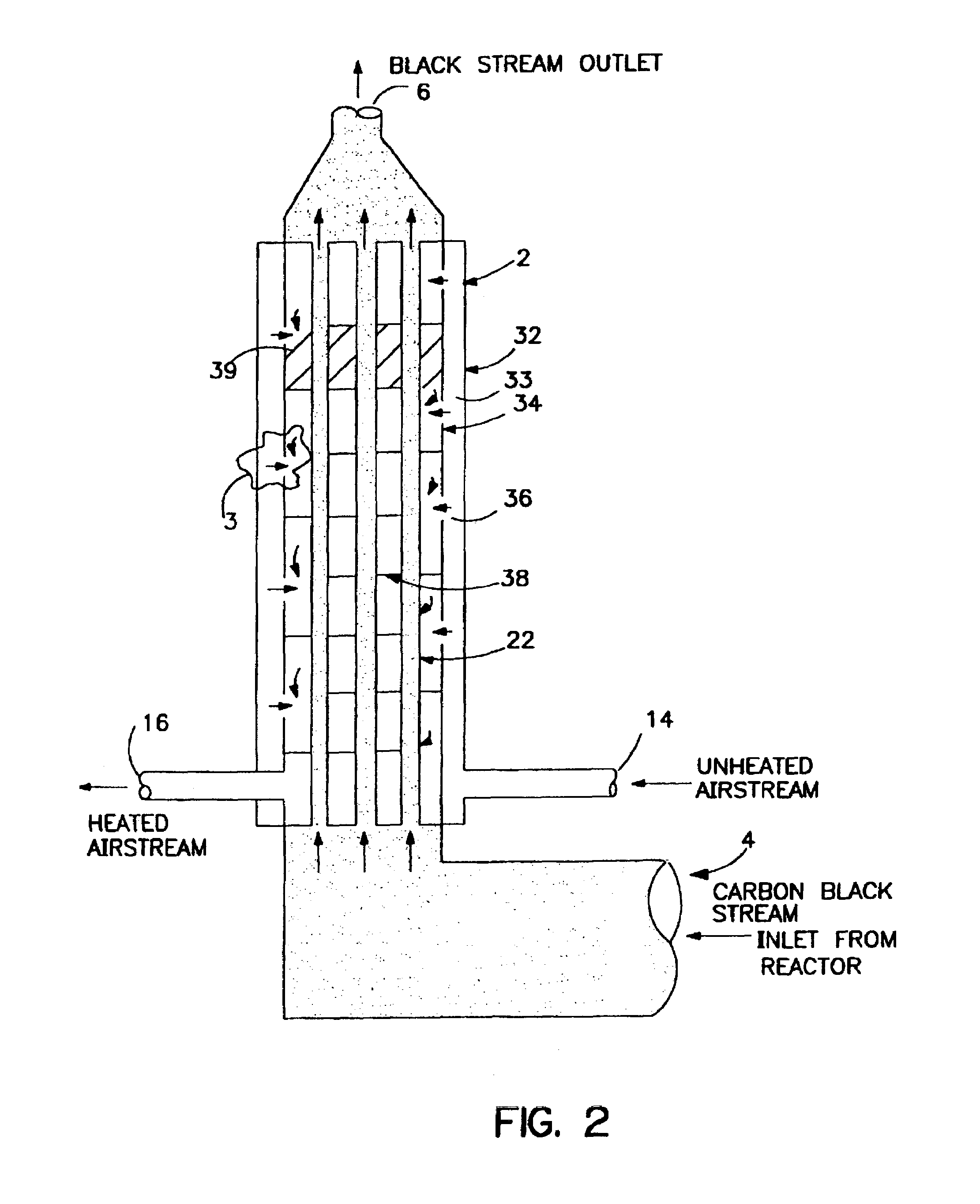
[0080]This example illustrates an embodiment heat exchanger of the present invention suitable for use as a combustion air heat exchanger in a carbon black production process and the advantages acheived by its use.

[0081]The features of the present invention were demonstrated on a carbon black unit with one reactor and one shell and tube heat exchanger (combustion air heat exchanger). Prior to use of a combustion air heat exchanger of the present invention, the unit had a conventional, counter-current, shell and tube heat exchange. It contained 40 tubes of 3.5 inches outside diameter, 50 feet in length and contained 33 baffles i.e. 34 baffle passes. The black stream was on the tubeside and the air stream was on the shellside. It was installed vertically so the black stream enters from the bottom. This heat exchanger normally fouled to a large extent, as shown by the large tubeside pressure drop. When the unit was periodically shutdown, it was observed that up to 35% of the tubes were ...


PUM

PropertyMeasurementUnit
temperatureaaaaaaaaaa

Abstract

An improved heat exchanger which resists fouling of the heat exchange surface by minimizing the temperature difference between the heat exchanger surface and the fluid stream in contact with the heat exchange surface. In one embodiment, a heat exchanger comprises an outer shell, the outer shell comprising a first inlet operable to pass a first fluid stream, an inner shell at least partially disposed within the outer shell, the inner shell comprising a second inlet and an outlet operable to pass the first fluid stream, and a heat exchange surface comprising a plurality of tubes operable to pass a second fluid stream.

Description

STATEMENT OF RELATED APPLICATIONS[0001]The present application is a divisional application under 35 USC §120 of U.S. patent application Ser. No. 08 / 627,880, filed Apr. 3, 1996 now U.S. Pat. No. 6,585,949.FIELD OF THE INVENTION[0002]The present invention relates to an improved heat exchanger. The heat exchanger of the present invention is advantageous for use in a carbon black production process.BACKGROUND[0003]Carbon blacks are generally produced in a furnace-type reactor by pyrolyzing a hydrocarbon feedstock with hot combustion gases to produce combustion products containing particulate carbon black. A variety of methods for producing carbon blacks are generally known.[0004]In one type of a furnace carbon black reactor, such as shown in U.S. Pat. No. 3,401,020 to Kester et al., or U.S. Pat. No. 2,785,964 to Pollock, hereinafter “Kester” and “Pollock” respectively, a fuel, preferably hydrocarbonaceous, and an oxidant, preferably air, are injected into a first zone and react to form ...

Claims


Application Information

Patent Timeline
Patent Type & Authority Patents(United States)
IPC IPC(8): F28D7/00F28F9/22C09C1/48C09C1/50F28F19/00F28F19/01
CPCC09C1/50F28F19/00F28F9/22C01P2006/19
Inventor GREEN, MARTIN C.SIFLEET, WILLIAM L.
Owner CABOT CORP
Learn More