
Hybrid radar receiver

a receiver and hybrid technology, applied in the field of hybrid radar receivers, can solve the problem that digital signals are not produced on each channel, and achieve the effect of reducing processor load

Inactive Publication Date: 2008-02-05
INFORMATION SYST LAB
View PDF21 Cites 11 Cited by
  • Summary
  • Abstract
  • Description
  • Claims
  • Application Information

AI Technical Summary

Benefits of technology

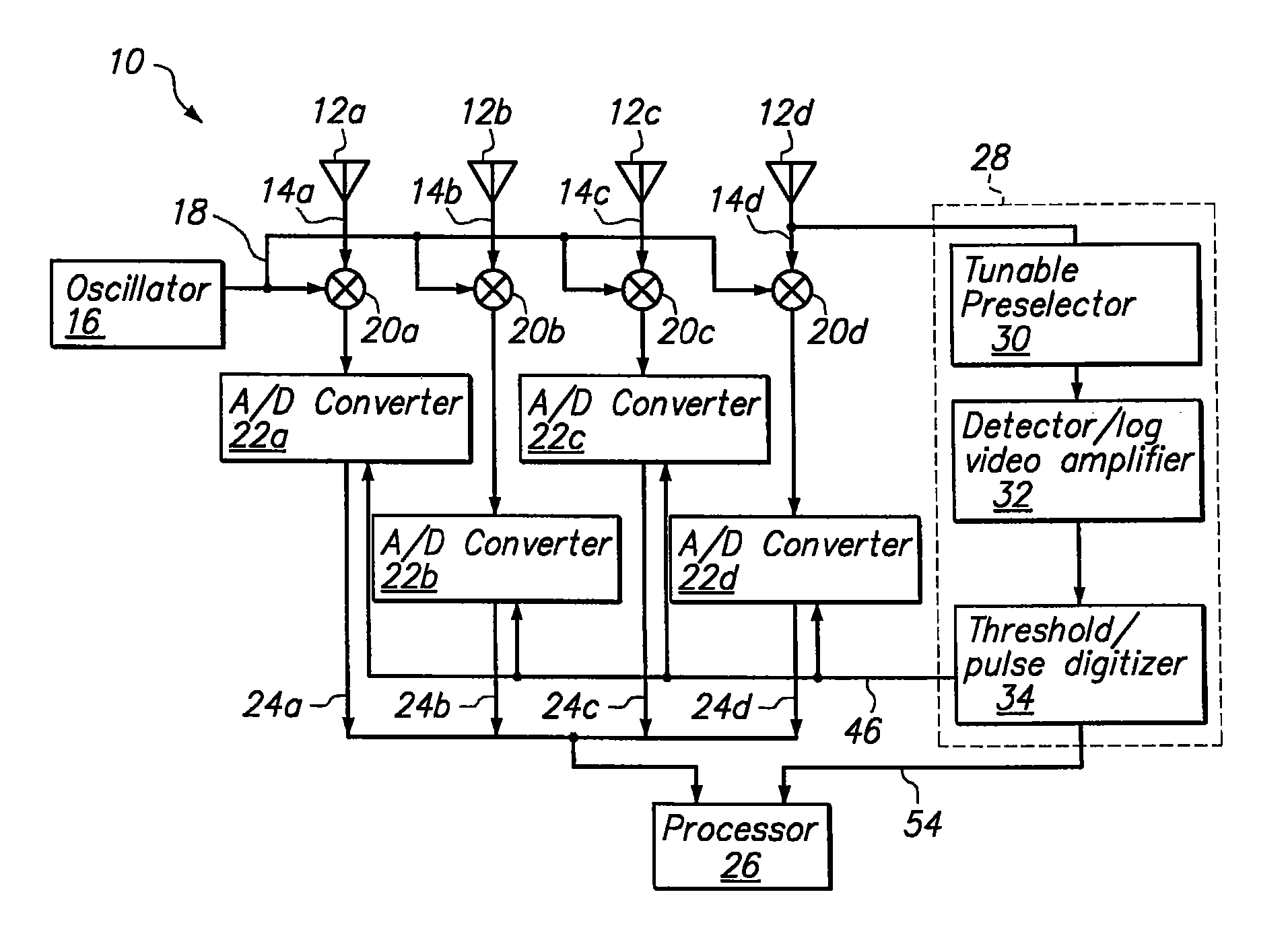
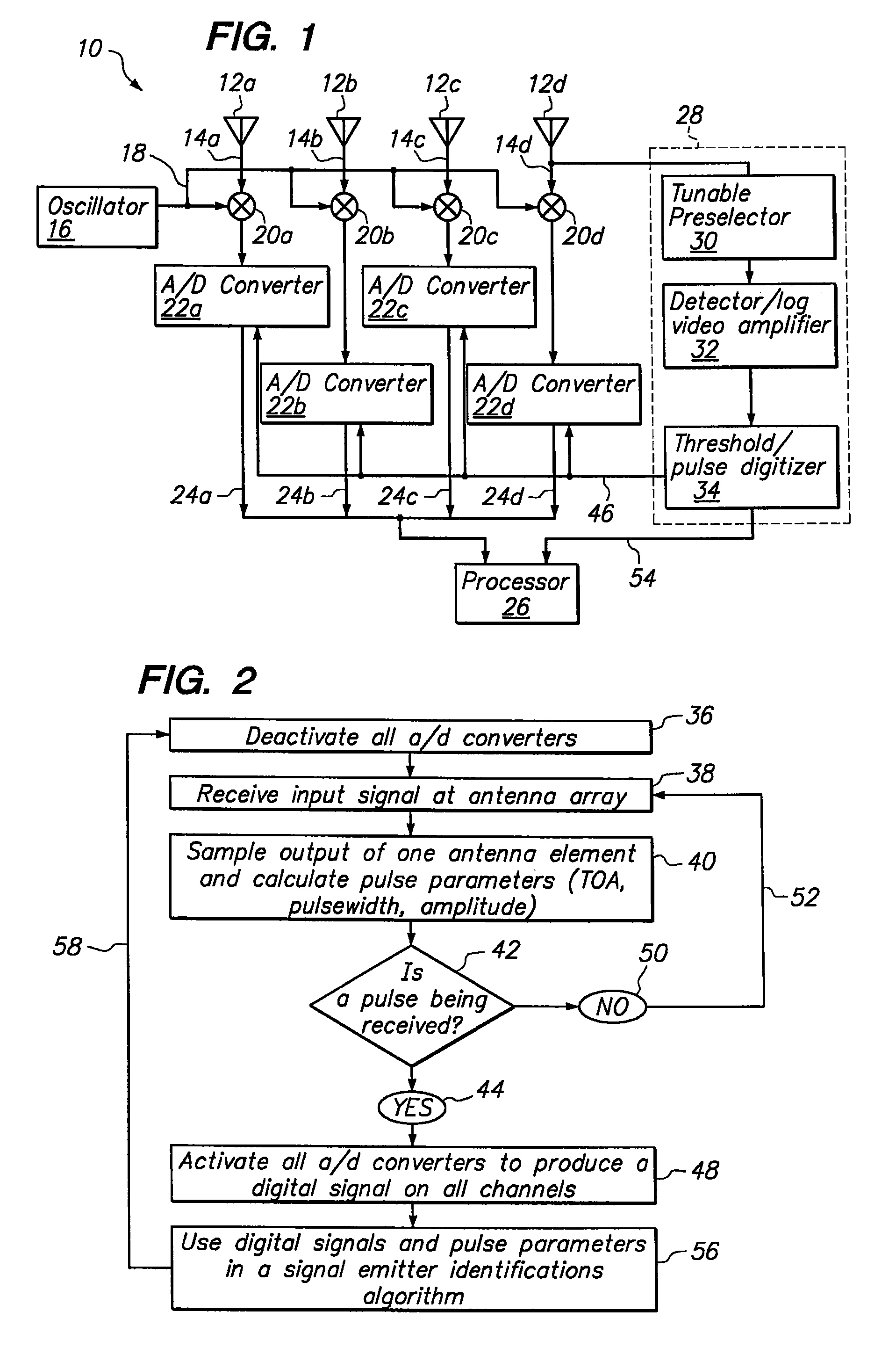
[0007]The present invention is directed to a hybrid radar receiver for receiving an input signal that includes a radar signal from at least one signal emitter. For the present invention, the receiver includes a plurality of antenna elements that are arranged as an antenna array. Each element in the array receives the input signal and generates an analog signal output on a respective data channel. For each data channel, an analog-to-digital (A / D) converter is provided to convert the analog signal on the channel to a digital signal. For the radar receiver, each A / D converter is switchable between an active state in which the converter generates a digital output and a non-active state in which the converter generates no output. More specifically, as detailed further below, all of the A / D converters are switched into the active state during periods when a pulse is being received and are switched into the non-active state during periods when a pulse is not being received. Thus, digital outputs are only generated during periods when pulses are received. This arrangement allows for a reduced processor load while maintaining the ability to coherently process across multiple antenna channels.

Problems solved by technology

On the other hand, when the circuit determines that a pulse is not currently being received, the circuit deactivates each A / D converter, and as a consequence, digital signals are not produced on each channel.

Method used


Image

  • Hybrid radar receiver
  • Hybrid radar receiver

Examples


Embodiment Construction

[0014]A hybrid radar receiver for identifying a signal emitter (e.g. target) is shown in FIG. 1 and is generally designated 10. As shown, the system 10 includes an antenna array having a plurality of antenna elements 12a-d. Although four antenna elements 12 are shown for the antenna array, it is to be appreciated that as few as two, and as many elements 12 as desired can be used for the receiver 10. It is further shown that each antenna element 12a-d produces an analog signal output on a respective channel 14a-d. A common local oscillator 16 is provided to mix a common oscillator signal 18 with the data on each channel 14a-d at respective mixing circuits 20a-d, as shown. This mixing is typically performed to down convert each signal from a respective antenna element 12a-d to a preselected intermediate frequency, or in some cases, to baseband.

[0015]FIG. 1 further shows that the receiver 10 includes an activatable analog-to-digital (A / D) converter 22a-d for each channel 14a-d. Digital...


PUM


Abstract

A hybrid radar receiver includes an antenna array for receiving an input signal having a radar signal from a signal emitter. Each array element outputs an analog signal on a respective data channel. For each data channel, an activatable A / D converter is provided. A dedicated hardware circuit, which typically includes a detector / log video amplifier that is coupled to a threshold / pulse digitizer, is included to determine when a radar pulse is being received. When the circuit determines that a pulse is being received, the circuit activates each A / D converter to generate a digital signal on each channel. When a pulse is not currently being received, the circuit deactivates each A / D converter and digital signals are not produced. Pulse parameter(s) generated by the hardware circuit and the digital signals on each channel are sent to a software equipped processor which implements a signal emitter identification algorithm.

Description

FIELD OF THE INVENTION[0001]The present invention pertains generally to radar receiver architectures. More particularly, the present invention pertains to a radar receiver architecture for receiving and analyzing wideband radar signals. The present invention is particularly, but not exclusively, useful as a hybrid radar receiver which reduces processor load by digitizing only a selected portion of an incoming wideband signal.BACKGROUND OF THE INVENTION[0002]The modern “electronic warfare” environment often includes a plethora of radar signals of varying frequency and bandwidth. Continuous digital sampling of this wideband signal environment to identify and characterize radar pulse trains on the received radar signals inevitably requires a high data sampling rate. This results in enormous amounts of data to be buffered and processed. Using current receiver architectures, the processing of this large amount of data generally requires an extremely complex, costly processor. On the othe...

Claims


Application Information

Patent Timeline
IPC IPC(8): G01S7/40G01S7/02G01S13/00
CPCG01S7/021
Inventor HALSEY, J. DOSSOHNISHI, KATSUMI
Owner INFORMATION SYST LAB
Learn More