
Window protection structure

a technology for windows and doors, applied in the direction of wing arrangements, door/window protection devices, shutters/movable grilles, etc., can solve the problems of high wind inside the home, damage to buildings (including homes), and windows and doors may break, so as to achieve the effect of simple and rapid method

Inactive Publication Date: 2008-02-05
WARNER JERALD R
View PDF7 Cites 29 Cited by
  • Summary
  • Abstract
  • Description
  • Claims
  • Application Information

AI Technical Summary

Benefits of technology

[0006]As will be amplified in greater detail hereinbelow, the present invention solves one of the prior art problems by providing a structure that allows a simple and rapid method for protecting windows and doors prior to a severe storm, such as a hurricane.
[0007]Accordingly, it is an object of the present invention to provide a simplified structure for protecting windows or doors of buildings against damage from high velocity winds during severe storms or hurricanes.
[0008]Another object of the present invention is to provide a structure that is easy and simple to install over windows or doors prior to a severe storm or hurricane and one that cinches tightly against the window to be protected.
[0009]Still another object of the present invention is to provide a structure that does not require the drilling of holes into the hose siding or window casing.
[0010]Yet another object of the present invention is to provide an inexpensive structure that is useful with a variety of window protection materials and one that is compatible with any type of home siding.

Problems solved by technology

As has been witnessed lately by a series of hurricanes, buildings (including homes) may be damaged or destroyed by high winds and high waves.
Debris can break windows and doors, allowing high winds inside the home.
In extreme storms, such as hurricanes, the force of the wind alone can cause weak places in ones home to fail.
However, such conventional installation procedures are time consuming and leave holes in the walls or window frames or sills.
Such holes are especially problematic where the walls of the house are vinyl or stucco.
The clips also allow installation and removal without the use of tools; however, these clips only work on brick, stone or concrete block structures.
Moreover, if wind gets behind the window covering, such as a sheet of plywood, the protection could be compromised and come loose.

Method used


Image

  • Window protection structure
  • Window protection structure
  • Window protection structure

Examples


Embodiment Construction

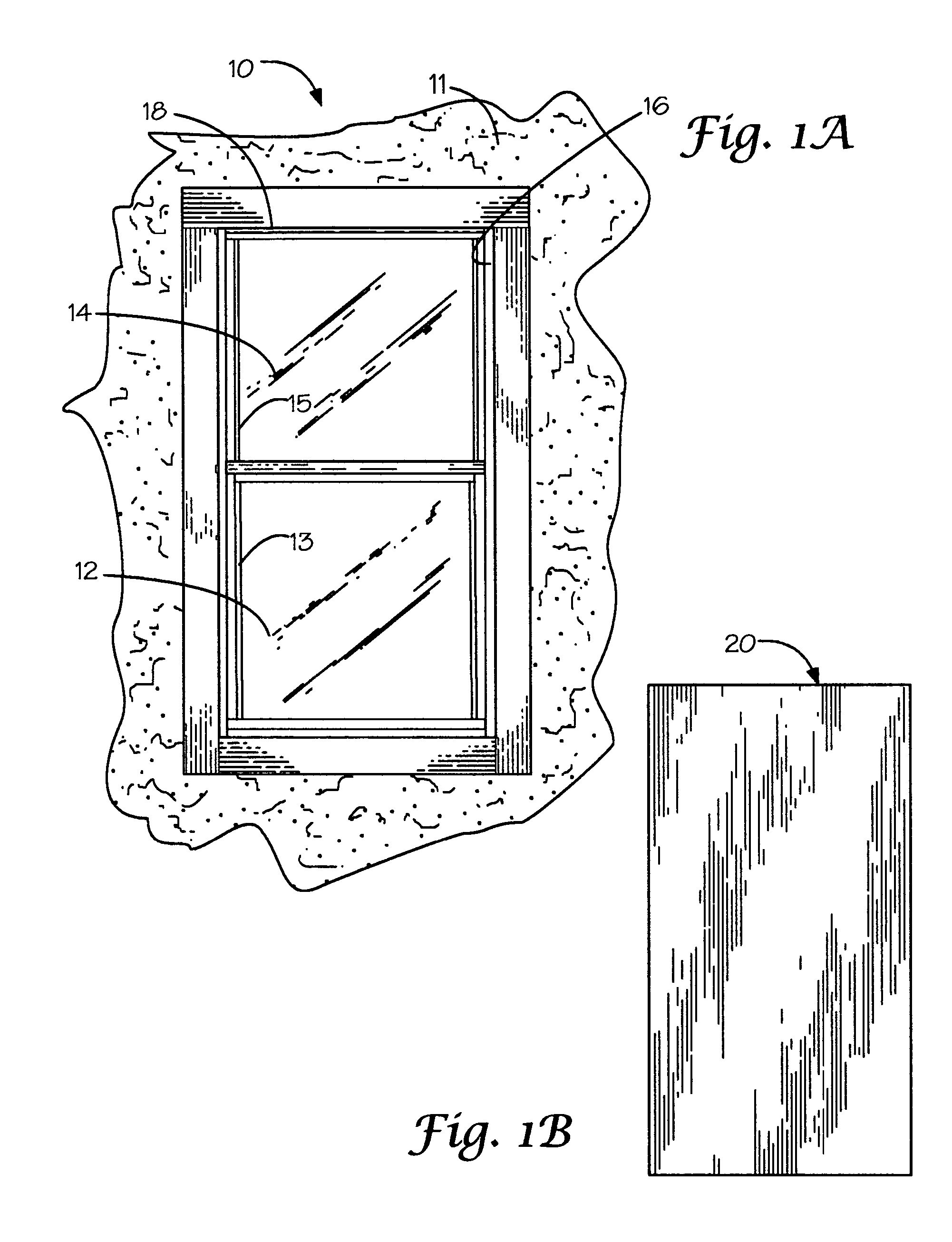
[0024]Referring now to the drawings, and to FIG. 1A in particular, an elevation of a window 10 to be protected by the structure of the present invention is shown. In the illustrated embodiment, window 10 is a conventional single-hung window in a building 11 having a lower window pane 12 supported by a lower frame 13 and an upper window pane 14 supported by a frame 15. The building 11 also includes a frame 16 formed therein for receiving the window 10. The window 10 includes an outer frame 18 that fits within the frame 16 for supporting the slidable lower and upper window frames 13 and 15, respectively.

[0025]It is pointed out, however, that the present invention has applicability to other types of windows and doors and is not limited to the illustrated embodiment.

[0026]FIG. 1B illustrates an elevation view of sheet material 20, which in one embodiment may be ⅝ inch plywood. The sheet material 20 may also comprise steel, aluminum, plastic or corrugated steel, clear plastic or the like...


PUM


Abstract

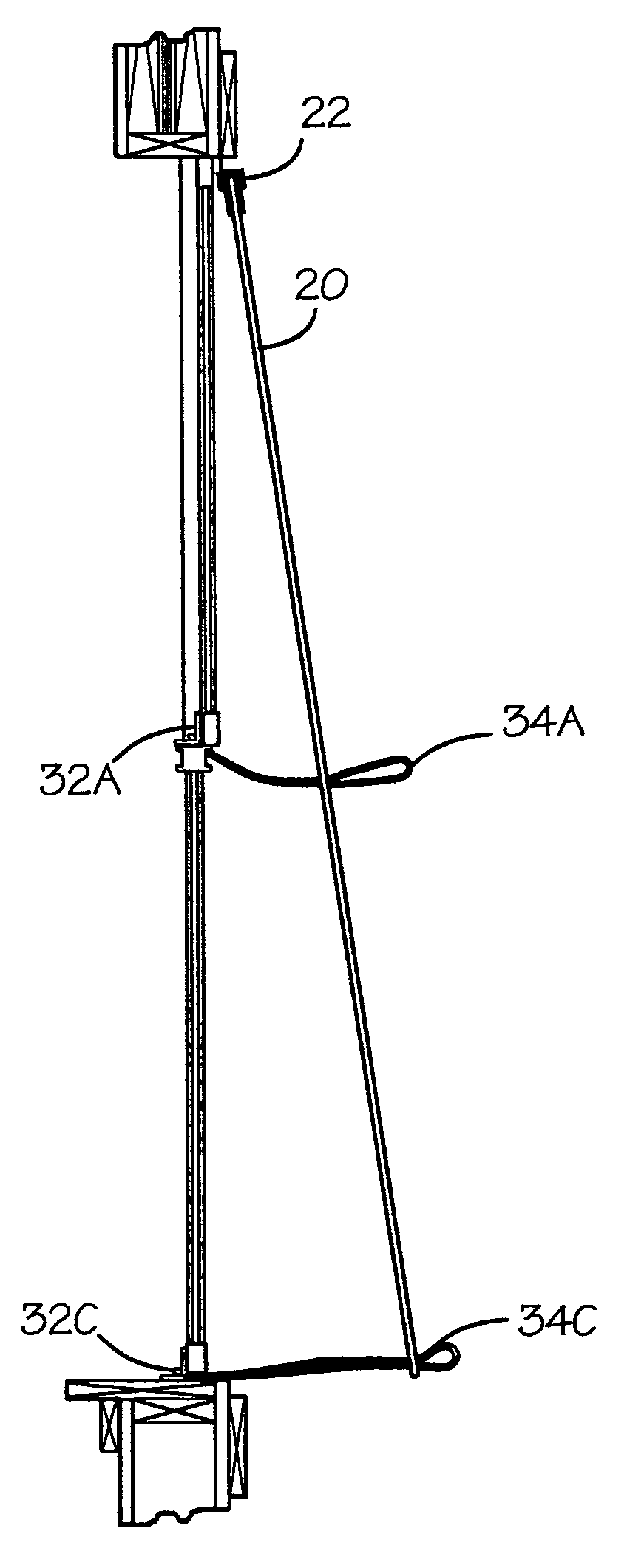
A window protection structure for a building including novel structure for affixing a sheet of protection material over the window opening. The sheet material is cut to the size of the window opening in the building, and holes are formed therein. U-shaped clips are slid onto an upper edge of the sheet material, and a plurality of brackets are provided with a pair of holes formed therein. Cords loops are secured through the holes in the brackets. The brackets are adapted for receipt by the interior of the window and the cords are threaded to the exterior of the window. The cord loops are threaded through the holes in the sheet material. A bungee cord is then used for securing the ends of the cord loops, whereby the sheet material is held firmly against the window.

Description

FIELD OF THE INVENTION[0001]The present invention generally relates to the field of storm protection and in particular to a structure for rapidly and easily inserting window protection prior to a severe storm, such as a hurricane or the like.BACKGROUND OF THE INVENTION[0002]As has been witnessed lately by a series of hurricanes, buildings (including homes) may be damaged or destroyed by high winds and high waves. Debris can break windows and doors, allowing high winds inside the home. In extreme storms, such as hurricanes, the force of the wind alone can cause weak places in ones home to fail. Experts have done extensive examination after hurricanes and have found four areas that should be checked for weakness—the roof, windows, doors and garage doors. The invention disclosed hereinbelow addresses a structure that allows rapid installation of protection over windows or doors, which structure is also referred to herein as storm shutters.[0003]Installing storm shutters over all expose...

Claims


Application Information

Patent Timeline
Patent Type & Authority Patents(United States)
IPC IPC(8): E06B9/02E06B3/26
CPCE06B9/02
Inventor WARNER, JERALD R.
Owner WARNER JERALD R
Learn More