
Linear ion trap for mass spectrometry

a technology of mass spectrometry and ion trap, which is applied in the direction of isotope separation, electric discharge tubes, separation processes, etc., can solve the problems of mass spectrometer efficiency and versatility suffer, the device performance is degraded, and the storage volume is limited, so as to achieve efficient and compact ion trap, efficient ejection of selected ions, and good ion storage volume

Active Publication Date: 2008-01-29
THE ROCKEFELLER UNIV
View PDF10 Cites 33 Cited by
  • Summary
  • Abstract
  • Description
  • Claims
  • Application Information

AI Technical Summary

Benefits of technology

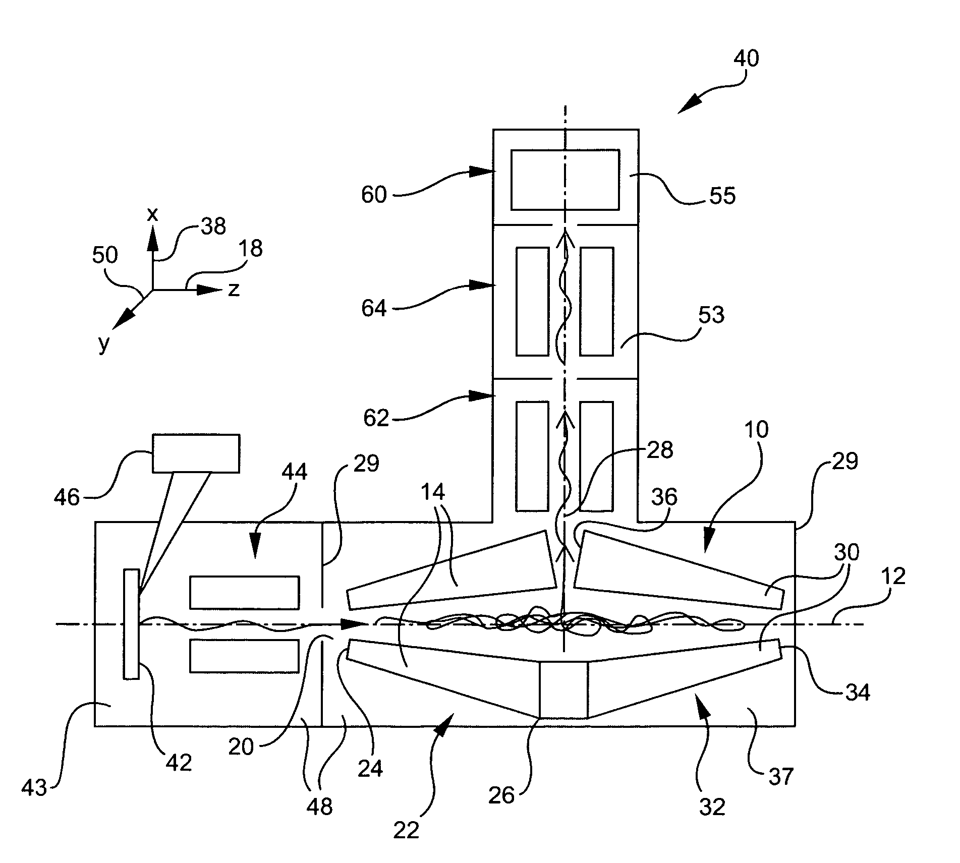
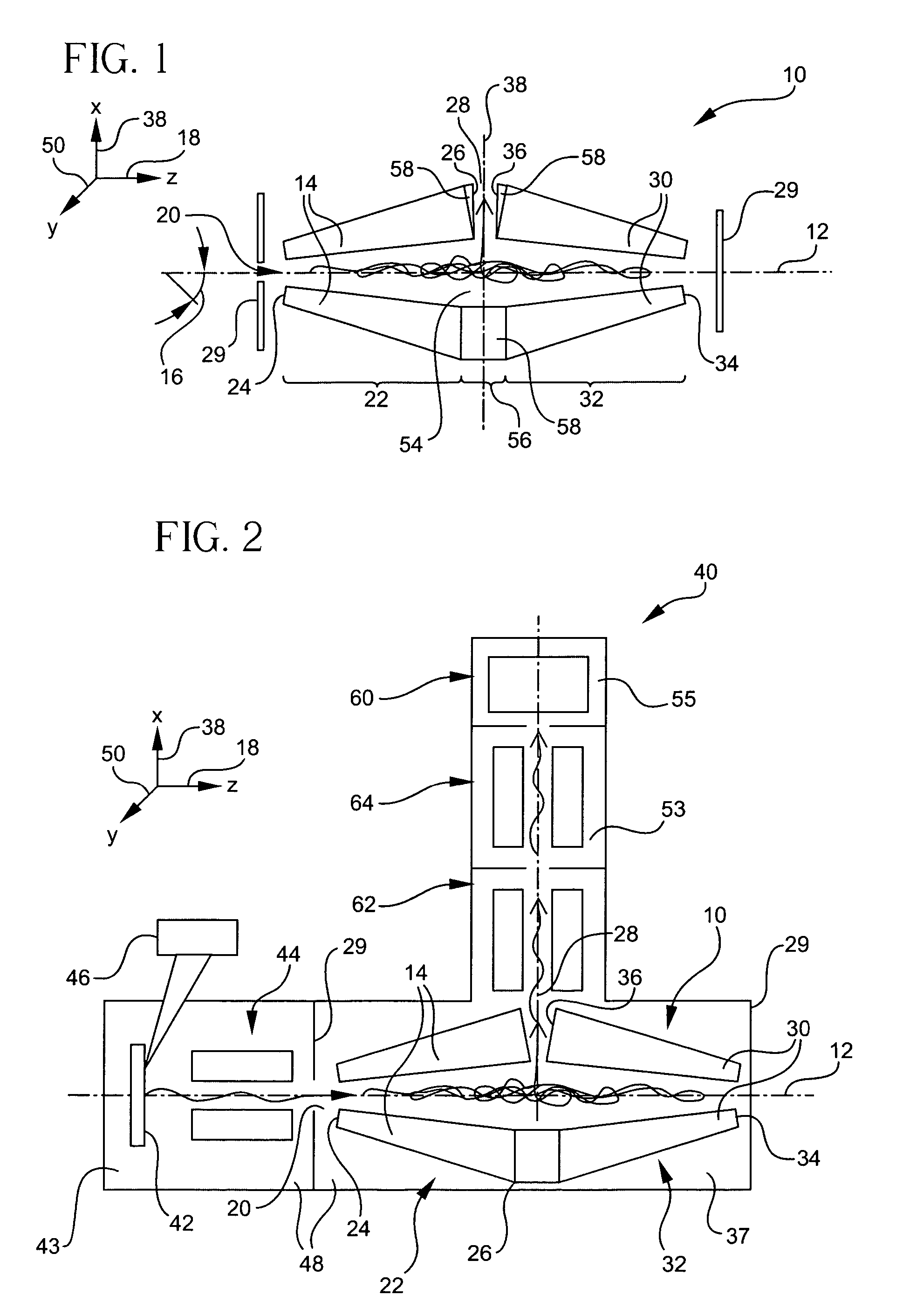
[0007]The present invention provides an efficient and compact ion trap and a method for manipulating ions in an ion trap. The ion trap and method provide both good ion storage volume and efficient ejection of selected ions. A high resolution, high sensitivity mass spectrometer that includes the ion trap is also provided.
[0017]As a result, the present invention provides an efficient and compact ion trap and a method for manipulating ions in an ion trap, which provide both increased ion storage volume and efficient ejection of selected ions. The ion trap may be adapted for use in a high resolution, high sensitivity mass spectrometer.

Problems solved by technology

The result is a degradation of performance of the device due to space charge effects, especially when attempting to trap large numbers of ions.
Though increased ion storage volume is provided by the ion trap geometry of the Bier, et al. patent, the efficiency and versatility of the mass spectrometer suffer, for example, due to the elongated slit and subsequent focusing of the ions required after ejection.
In addition, the storage volume is limited by practical considerations, since the length of the spectrometer must be increased in order to increase the ion storage volume.

Method used


Image

  • Linear ion trap for mass spectrometry
  • Linear ion trap for mass spectrometry
  • Linear ion trap for mass spectrometry

Examples


embodiment 160

[0117]FIG. 14 shows a further embodiment 160 of a one-armed ion trap formed in accordance with the present invention, with an ejection port 162 parallel to the injection port 164, providing axial ejection of the ions from the ion trap 160. The ion trap 160 includes two pairs of opposing electrodes 166 in the arm of any shape and geometry that will satisfy equation (1) and (2) as described herein. The ion trap 160 optionally includes a section of a linear conventional quadrupole (not shown), including two pairs of parallel opposing electrodes connected to the electrodes 166 and including the axial ejection port 164. The ion trap 160 also includes a mesh stopping plate 168, to which a DC potential is applied for containment of the ions during ramp up. The axial ejection can be achieved similarly by applying dipolar excitation and ramping up an RF voltage, for example, or by applying an auxiliary alternating current (AC) field to the plate 168 during ejection. Such methods are known in...

embodiment 190

[0127]An additional embodiment 190 of the ion trap of the present invention is provided in FIG. 16, which includes five arms 192 in a star configuration, each arm including two pairs of opposing electrodes tilted at some angle to the axis of symmetry 12 of each arm. As shown, the electrodes of each arm are preferably tapered, and may be tapered cylindrical rods as shown. The simulated ion trajectories 194 are shown. The injection port 196 may be along one or more of the axes of the four outer arms with wider ends facing inward. The ejection port is preferably oriented at the center 198 of the star configuration, and at the wide end of the central arm 200.

[0128]In addition to its usefulness in a mass spectrometer, the ion trap of the present invention may also be used for building ion-ion and ion-cation reactors.

[0129]In another embodiment, the ion trap of the present invention may be used to isolate ions for a given M / Z for other purposes such as optical spectroscopy or for use in p...


PUM


Abstract

A method for manipulating ions in an ion trap includes storing ions, spatially compressing, and ejecting selected ions according to mass-to-charge ratio. An ion trap includes an injection port, an arm having a first and a second end for confining and spatially compressing the ions, and an ejection port for ejecting the ions from the second end. The arm includes two pairs of opposing electrodes, which provide a quadrupole electric field potential at any cross-section of the ion trap. The distance between opposing electrodes and the cross-sectional area of the electrodes increases from the first to second end. The electrodes may be tapered cylindrical rods or of hyperbolic cross-section. Ions selected for ejection are spatially compressed into a region at the second (wider) end. The ion trap may include one arm, with either orthogonal or axial ejection, or two arms with a central insert for orthogonal ejection.

Description

GOVERNMENTAL SUPPORT[0001]The research leading to the present invention was supported, at least in part, by NIH Grant No. RR 00862. Accordingly, the United States Government has certain rights in the invention.BACKGROUND OF THE INVENTION[0002]The present invention relates to ion traps for mass spectrometry, and in particular, to a linear ion trap device for efficient storage of ions providing high sensitivity, rapid, high efficiency mass spectrometry.[0003]Ion trap mass spectrometers have conventionally operated with a three-dimensional (3D) quadrupole field formed, for example, using a ring electrode and two end caps. In this configuration, the minimum of the potential energy well created by the radio-frequency (RF) field distribution is positioned in the center of the ring. Because the kinetic energy of ions injected into an ion trap decreases in collisions with buffer gas molecules, usually helium, the injected ions naturally localize at the minimum of the potential well. As has ...

Claims


Application Information

Patent Timeline
Patent Type & Authority Patents(United States)
IPC IPC(8): B01D59/44H01J49/00
CPCH01J49/423
Inventor KRUTCHINSKY, ANDREW N.COHEN, HERBERTCHAIT, BRIAN T.
Owner THE ROCKEFELLER UNIV
Learn More