Sphering apparatus and operating method thereof

a technology of sphering apparatus and operating method, which is applied in the direction of glass rolling apparatus, instruments, manufacturing tools, etc., can solve the problems of difficult to equalize qa and qb, difficult to always maintain a constant q, and difficult to make the right timing for increasing and decreasing quantities

Active Publication Date: 2010-08-31
NIPPON SANSO CORP
View PDF10 Cites 0 Cited by
  • Summary
  • Abstract
  • Description
  • Claims
  • Application Information

AI Technical Summary

Benefits of technology

[0042]Herein, it is preferable for the pressure in the furnace 10 to be a negative pressure. In this case, it is possible to adjust the suctioning amount upstream of the cyclone 20 and the pressure in the furnace 10 by adjusting the gate opening of the second damper 23. Therefore, it is possible to prevent the particles from adhering to the inner wall of the furnace 10 and to efficiently eject the particles from the furnace 10 in addition to the aforementioned advantageous effects of adhesion preventing air.
[0043]The control unit 50 controls a pressure and a temperature of the gas in the sphering furnace 10, and is composed of a pressure indicating controller (PIC) 51, a temperature indicating controller (TIC) 52, and a computing unit (Y) 53. This control unit 50 is connected to the pressure sensor 15, the first temperature sensor 16, the second temperature sensor 24, the first damper 43, the second damper 23, and the third damper 33 through communication cables. Herein, wireless communication can be applied instead of communication cables as the connecting method between the control unit 50 and each of the constituent elements.
[0044]Hereinafter, an example of the operating method of the sphering apparatus using the control unit 50 is described.
[0045]Pressure and temperature values measured by the pressure sensor 15, the first temperature sensor 16, and the second temperature sensor 24 are transmitted to the control unit 50 and inputted to the computing unit 53. In this computing unit 53, the computation is carried out on the basis of the inputted pressure and temperature values and the pressure and temperature values predetermined in the pressure indicating controller 51 and the temperature indicating controller 52. Then, gate opening-controlling signals are transmitted from the control unit 53 to the first damper 43, the second damper 23, and the third damper 33 so as to equalize the measured pressure and temperature values and the predetermined pressure and temperature values, and then the gate opening thereof are controlled.
[0046]Herein, the aforementioned control is carried out automatically and continuously.
[0047]The relationship between the gate opening of each damper, and the temperature and the pressure at the upper part in the furnace 10 is described in Table 1.

Problems solved by technology

However, there is the problem in that it is difficult to equalize ΔQa and ΔQb.
As described above, it is difficult to always maintain a constant Q because the pressure in the furnace 10 varies due to the increased and decreased quantities of Qa and Qb.
Even if adjustment of the rotational frequencies of the blowers 40a and 40b is attempted at the same time in accordance with the increased and decreased quantities of Qa and Qb, it is very difficult to make the right timing for increasing and decreasing quantities of Qa and Qb, and there is the problem in that the trapping efficiency of the cyclone 20 cannot be prevented from being lowered by the change in Q.
As a result, there is problem in that the quality and the production efficiency of the particles are deteriorated.

Method used


Image

  • Sphering apparatus and operating method thereof
  • Sphering apparatus and operating method thereof
  • Sphering apparatus and operating method thereof

Examples


example 1

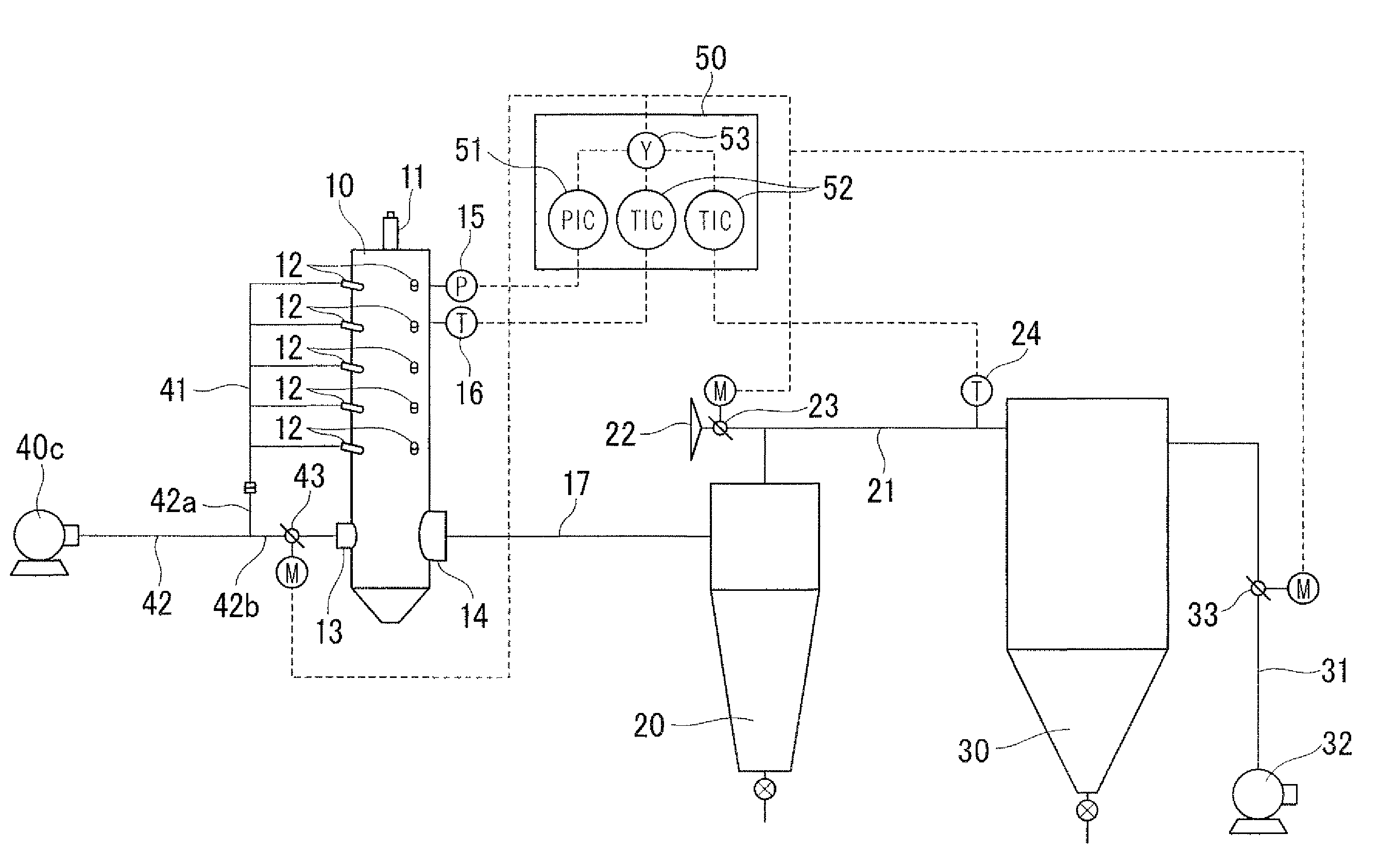
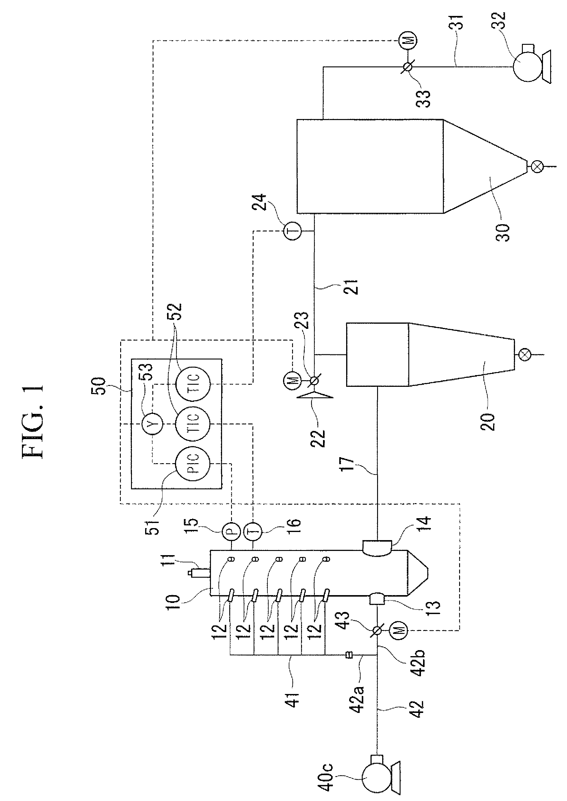
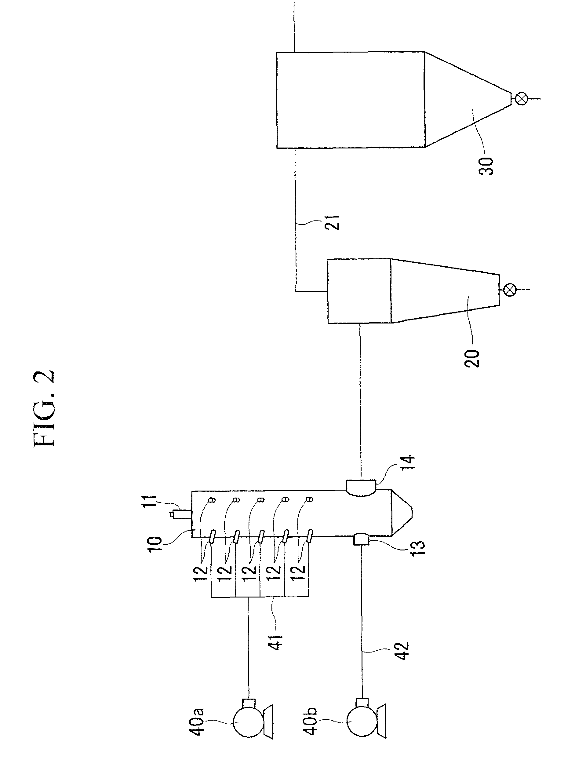
[0053]In Example 1 the particle production tests were carried out using the sphering furnace of the present invention represented by FIG. 1 and the conventional sphering furnace represented by FIG. 2, and both tests were compared.

[0054]As the furnace 10, a furnace was used with an inner diameter of 600 mm and a height (length) of 3,000 mm, on the inner wall of which four vertical rows of the adhesion-preventing air-introducing holes 12, 12, were formed along the circumferential direction and five of the adhesion-preventing air-introducing holes 12, 12, . . . were formed in each of the vertical rows. Adhesion preventing-air was blown at 100 Nm3 / h through each of the adhesion-preventing air-introducing holes 12, 12, . . . so as to evenly distribute adhesion preventing-air on the inner wall of the furnace 10.

[0055]As raw material powder, silica powder was used.

[0056]In the case of producing spherical silica particles, the preferable temperature range and pressure range at the upper par...


PUM

PropertyMeasurementUnit
temperatureaaaaaaaaaa

Abstract

A sphering apparatus includes a sphering furnace on a body of which a plurality of adhesion preventing air-introducing holes is formed and at a lower position of which a carrier air-introducing hole and a carrier air-withdrawing hole are formed; an air blower introducing both an adhesion preventing air and a carrier air; a first pipe one end of which is connected to a discharging part of the air blower and the other end of which is biforked, one biforked end being connected to the carrier air-introducing hole and the other biforked end being connected to a manifold bundling the plurality of adhesion preventing air-introducing holes; a first damper provided in any one of two pipes in the biforked part of the first pipe; a cyclone connected to the carrier air-withdrawing hole through a second pipe; and a bag filter connected to the cyclone through a third pipe.

Description

[0001]This application is the U.S. national phase of International Application No. PCT / JP2005 / 017473, filed 22 Sep. 2005, the entire contents of each of which are hereby incorporated by reference.TECHNICAL FIELD[0002]The present invention relates to an improvement of an apparatus which produces inorganic spherical particles (hereinafter referred to as a “sphering apparatus”) which supplies a raw material inorganic powder (hereinafter referred to as a “raw material”) such as silicon dioxide (SiO2) into flames, thereby producing inorganic spherical particles (hereinafter referred to as “particles”).BACKGROUND ART[0003]As an example of a conventional sphering apparatus, the sphering apparatus described in Japanese Patent Publication No. 3331491 is shown in FIG. 2. This sphering apparatus is composed of a sphering furnace 10, a cyclone 20, and a bag filter 30.[0004]The sphering furnace 10 (hereinafter referred to as “furnace 10”) melts the raw material in flames, thereby forming particl...

Claims


Application Information

Patent Timeline
Patent Type & Authority Patents(United States)
IPC IPC(8): G06F19/00C03B13/14C03B9/00B01J2/00B01J2/02B01J19/00C01B13/14C01B33/18
CPCC01B33/12B01J2/00
Inventor HAGIWARA, YOSHIYUKIMIYAKE, SHINICHI
Owner NIPPON SANSO CORP
Why Eureka
Try Eureka