[0013]Based upon the above determinations, various systems and processes can be provided. These include optical torque and joint integrity applications, dynamic sensing to predict shaft
cracking and / or breakage, automatic misalignment, severity detection, and / or associated dynamic correction for rotating machinery applications. Other applications include motor alignment, mounting integrity, and seal analysis via bi-refringent
optical coupling, for example. Still other applications include
load sensing for vehicle steering and drive
train components. For example, integrated intelligent steering systems can be utilized to enable highly responsive, reliable, and safe steering on various rough and slippery surfaces by sensing driver commanded torque and wheel / steering loading. Such systems can be employed in a closed-loop steer-by-wire system.
[0014]Thus, the present invention provides flexible and robust systems and methods for determining a plurality of characteristics for rotating machinery while facilitating various automatic correction procedures relating thereto.
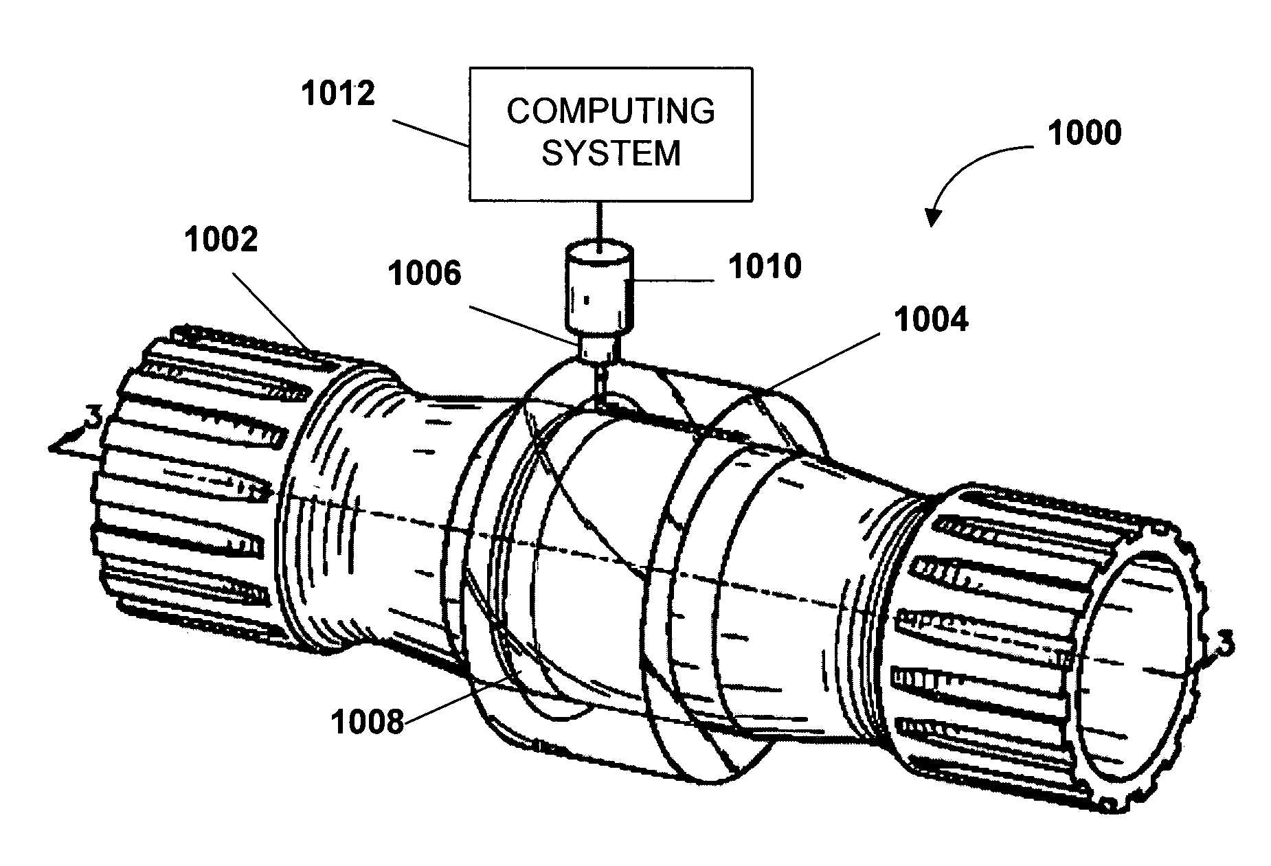
[0015]In accordance with one aspect of the present invention, a portion of a rotating shaft is encompassed by a sleeve of photo-elastic material, wherein the photo-elastic sleeve is attached to the shaft. For example, the photo-elastic sleeve can be cast, machined, attached with
adhesive, or even sprayed onto the shaft. A
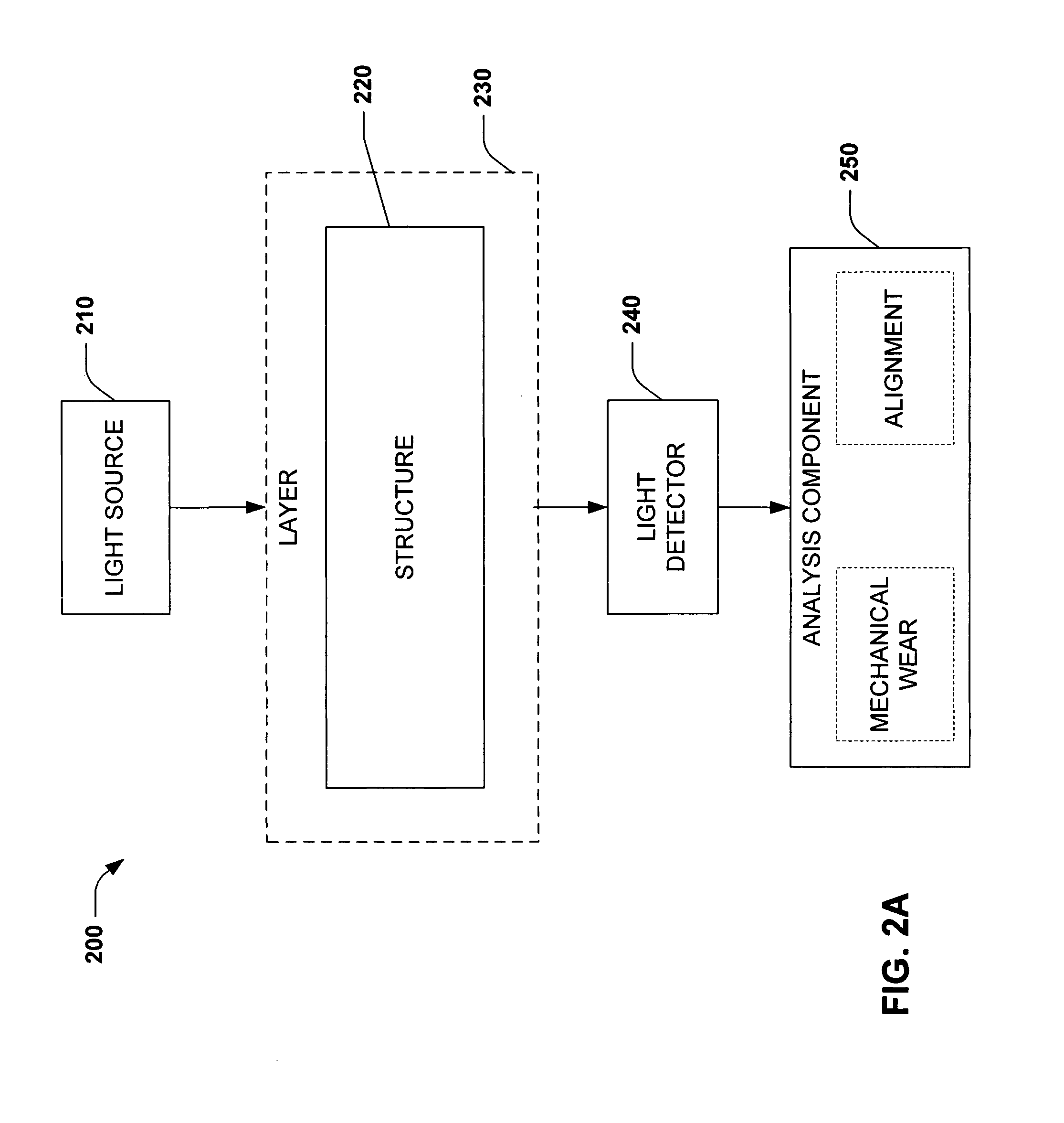
light source is employed to deliver light that will travel along the axis of the shaft through the photo-elastic sleeve. The
light source can be placed at any suitable angle to the rotating shaft, so long as the light delivered is redirected through the photo-elastic sleeve along the axis of the shaft. For instance, a
light source can be configured to deliver light perpendicularly to the shaft into the photo-elastic sleeve, wherein the light is redirected by a reflective notch (e.g., v-groove)
cut at an angle (e.g., 45°) to the light source, thereby redirecting the light along the axis of the shaft. V-groove faces can optionally be covered with a thin strip of reflective material (e.g., Mylar®) to provide a
specular surface with minimal light
distortion. At least one end of the collar of the photo-elastic material can be coated with a reflective substance (e.g., aluminum filled
epoxy), thus requiring a beam of light emitted from a light source to reflect back along the same path. For example, having a beam of light
traverse a longer path through the photo-elastic material such as twice the
axial length (e.g., once prior to reaching the reflective edge and once upon reflection) results in a more accurate and thorough analysis of
mechanical wear of the shaft.
[0017]Since a number of fringes increases linearly with
optical path length, sensitivity of the
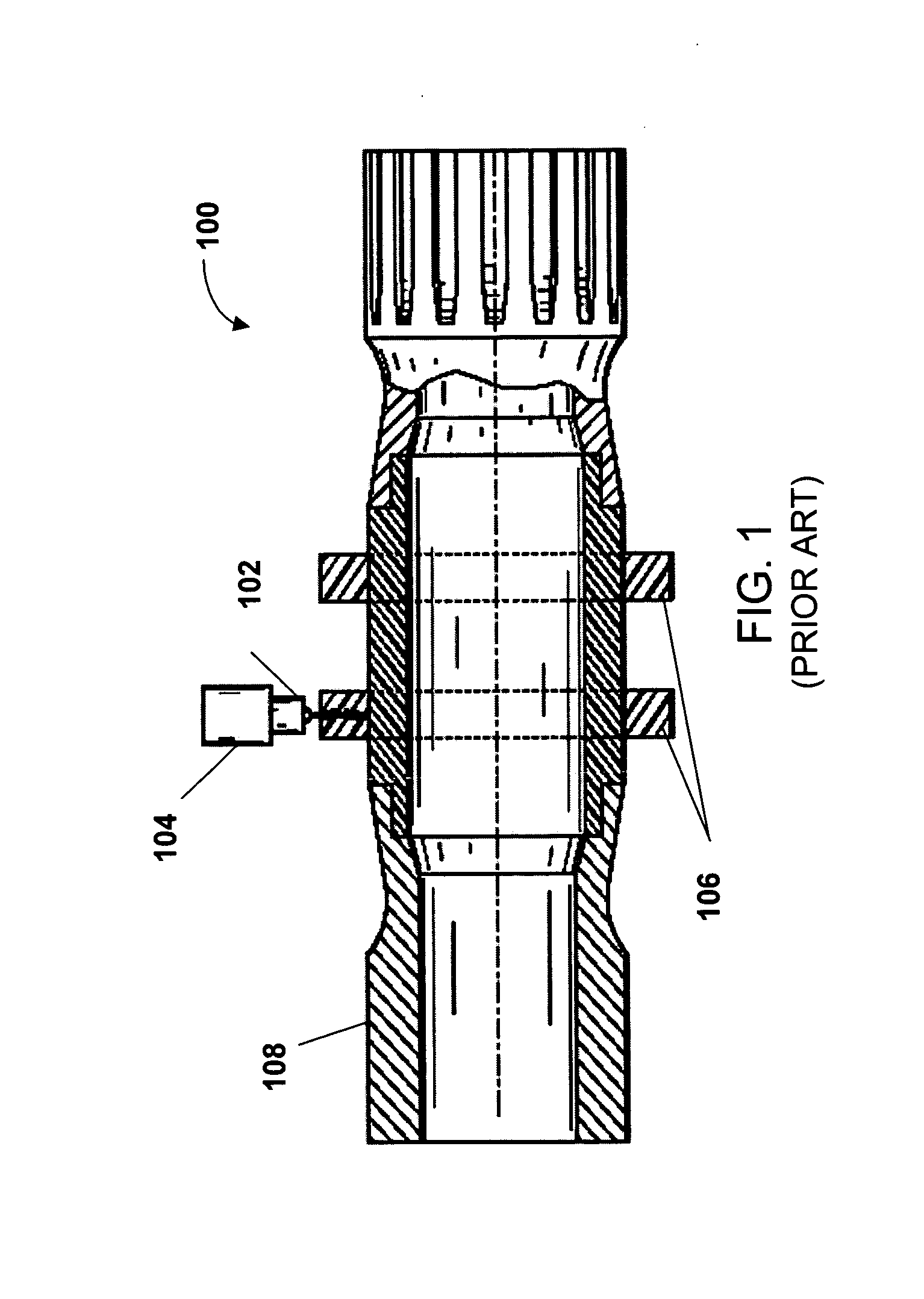
optical sensing system is also increased as a function of length of the photo-elastic material. In the prior art, by restricting the light direction to be only radial, the
path length of the beam was limited to two times the thickness of the photo-elastic collar. However, it is desirable to keep the collar relatively thin to avoid problems with collar mounting, minimize vibration, minimize forces during rotation, and avoid
optical distortion from thick materials. Additionally, it is to be understood that a reflective substance on a collar of the photo-elastic sleeve is not required to practice the invention, as strain on the shaft can be determined when a beam of light passes through an end photo-elastic sleeve and data collected at such end as compared to the light reflecting backward from such end
[0019]In yet another aspect of the present invention, an imminent failure condition can be relieved by employing a
feedback control system wherein a corrective measure is made without
human interaction. For example, if a rotating shaft is misaligned along its axis, a
smart material can be employed at either end to re-align the shaft and place it within desired operating parameters. Thus, a lateral or axial misalignment can be corrected by employing a closed-
loop control system. Feedback from an alignment sensor can confirm that the shaft is aligned and can facilitate subsequent control actions required to maintain alignment in the event of
thermal deformation, wear, or loading changes.


