
Signal intensity range transformation apparatus and method

a signal intensity range and transformation apparatus technology, applied in the field of image data manipulation systems, can solve the problems of not being able to enhance the higher frequency structure of interest and not being able to optimally recognize the spatial structure, and achieve the effect of improving human interpretation of the resultant imag

Inactive Publication Date: 2008-01-22
RYTEC CORP
View PDF351 Cites 12 Cited by
  • Summary
  • Abstract
  • Description
  • Claims
  • Application Information

AI Technical Summary

Benefits of technology

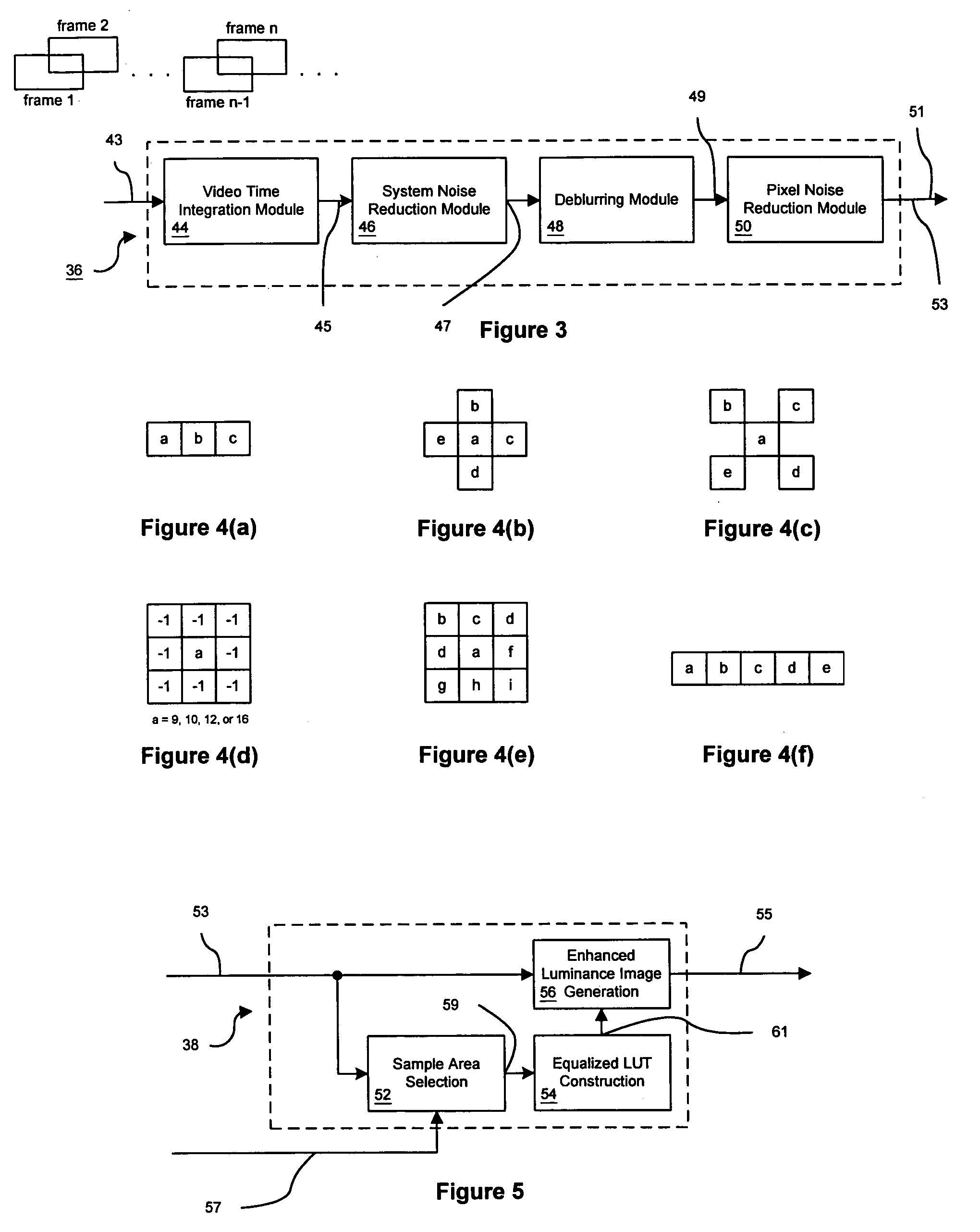
The present invention is a system and method for improving the interpretation of images from video or other sources by considering the mechanisms and defects of the image. The invention proposes a method for redistributing discrete signal intensity values within groups of signal intensity values that have spatial or geometrical relationships to each other. This can be applied to various sensing modalities such as magnetic resonance imaging, radar, sonar, infrared, ultraviolet, microwave, X-ray, radio wave, and the like. The invention also proposes generating subset partitions of an image representative of the spatial scales of interest and using efficient interpolation to produce the correct transform representation at each pixel. Additionally, the invention provides apparatus and methods for blending transformed values from the global set of values with transformed values from the spatial segments to adjust contributions from several spatial scales as desired. The invention can be used to enhance luminance contrast in video signals by applying various operators such as digital sampling, luminance / color separation, noise reduction, deblurring, pixel noise reduction, histogram smoothing, contrast stretching, and luminance and chrominance re-combination with configurable attributes.

Problems solved by technology

Often, this single global mapping has to stretch to map all of the low frequency variation in the image, and then fails to enhance higher frequency structure of interest.
As such, there may not be optimal recognition of spatial structure because of the need to represent the large scale variation across the entire image.

Method used


Image

  • Signal intensity range transformation apparatus and method
  • Signal intensity range transformation apparatus and method
  • Signal intensity range transformation apparatus and method

Examples


Embodiment Construction

[0029]This invention is susceptible of embodiments in many different forms. For example, the methods and apparatus disclosed there is shown in the drawings and will herein be described in detail, a preferred embodiment of the invention. The present disclosure is to be considered as an exemplification of the principles of the invention and is not intended to limit the broad aspect of the invention to the embodiment illustrated.

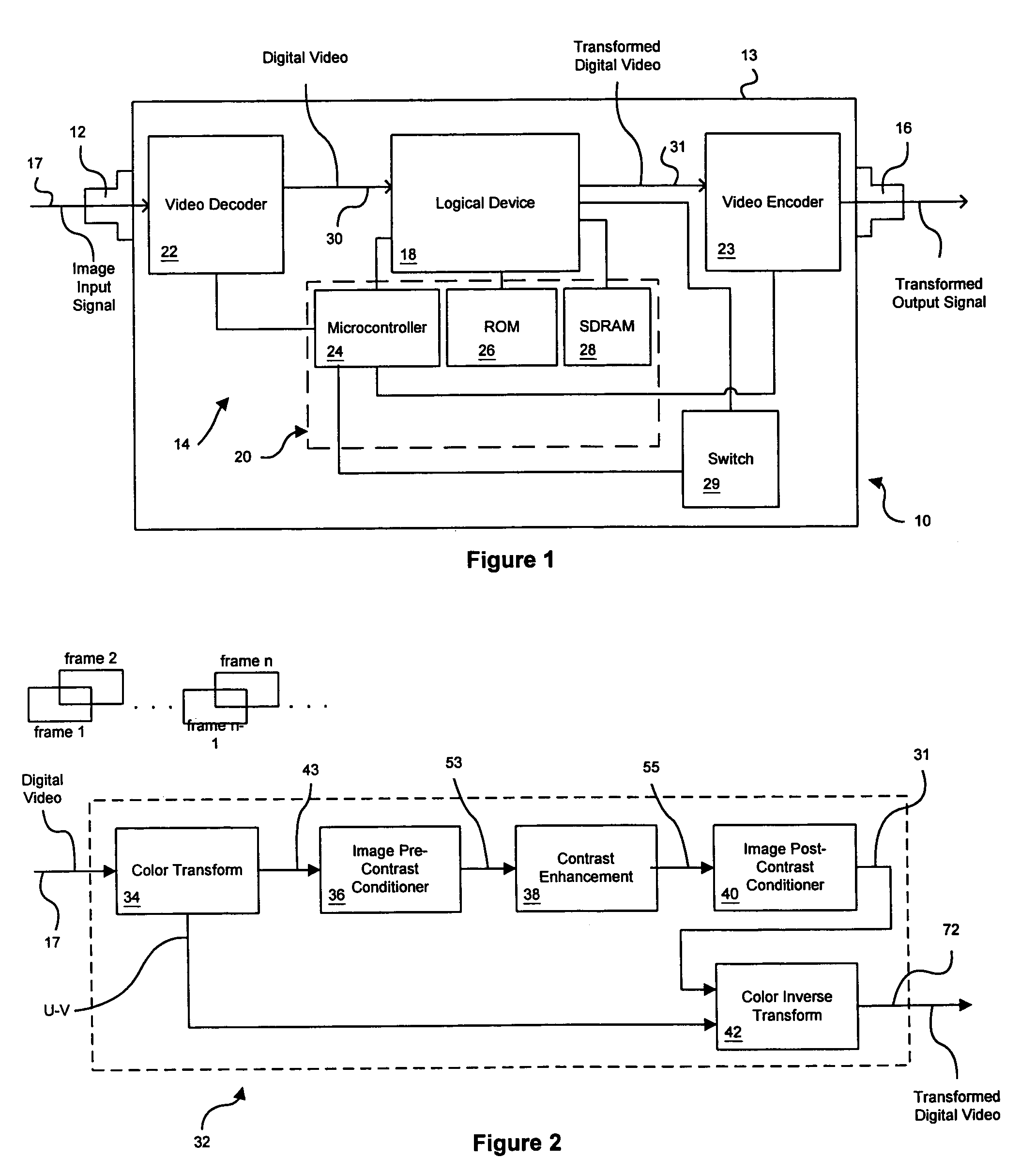
[0030]Referring now to the drawings, and as will be appreciated by those having skill in the art, each of the FIGURES depicts a simplified block diagram wherein each block provides hardware (i.e., circuitry), firmware, software, or any combination thereof that performs one or more operations. Each block can be self-contained or integral with other hardware, firmware, or software associated with one or more other blocks.

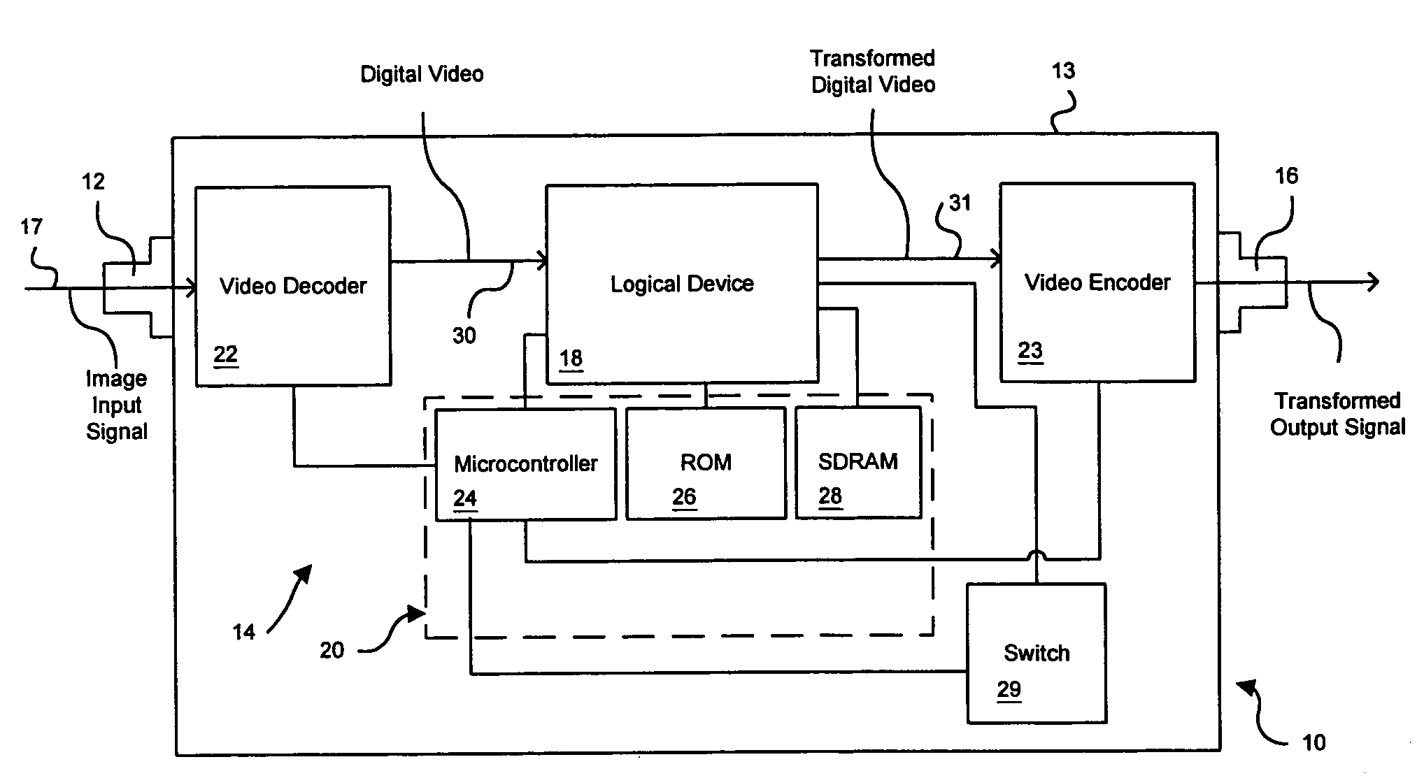
[0031]Turning particularly to FIG. 1, a device 10 is disclosed for enhancing, through transformation, the luminance range of an image input sign...


PUM


Abstract

A system and method for manipulating image data is disclosed. Generally, the system and method identifies useful grey-levels within an input image. The image is then scaled based upon the identified useful grey-levels.

Description

RELATED APPLICATIONS[0001]This application claims the benefit of U.S. Provisional Application No. 60 / 408,663, filed Sep. 6, 2002, and herein incorporated by reference.TECHNICAL FIELD[0002]The present invention generally relates to imaging systems, and in particular, to a system for manipulating image data.BACKGROUND OF THE INVENTION[0003]Human interpretation of video or other imagery can be made difficult or even impossible by system noise, image blur, and poor contrast. These limitations are observed, for example, in most video and closed circuit television systems, and others, including such technology as RS-170 monochrome video, NTSC / PAL / SECAM video or digital color video formats.[0004]Extreme lighting variation, for example, due to sunlight beams, can cause typical video cameras and imaging sensors to saturate (i.e., become unable to represent the real-world luminance range) resulting in wide-scale bright and dark regions having extremely low-contrast wherein objects are difficu...

Claims


Application Information

Patent Timeline
Patent Type & Authority Patents(United States)
IPC IPC(8): G06K9/40H04N1/40G06T5/00G06T5/40H04N5/20H04N9/64
CPCG06T5/008G06T5/40H04N5/20G06T5/002G06T2207/10016G06T2207/20032H04N9/64G06T5/94G06T5/70H04N23/84
Inventor JOHNSON, STEPHEN G.ELSDOERFER, NORBERT W.ANASTASIA, CHARLES M.
Owner RYTEC CORP
Learn More