
Sound absorptive multilayer composite

a multi-layer composite and sound absorption technology, applied in the direction of synthetic resin layered products, flooring, building components, etc., can solve the problems of suboptimal design acoustic performance and achieve low additional thickness or weight penalties, improve acoustic performance, and reduce vehicular interior noise levels.

Active Publication Date: 2008-01-22
3M INNOVATIVE PROPERTIES CO
View PDF200 Cites 79 Cited by
  • Summary
  • Abstract
  • Description
  • Claims
  • Application Information

AI Technical Summary

Benefits of technology

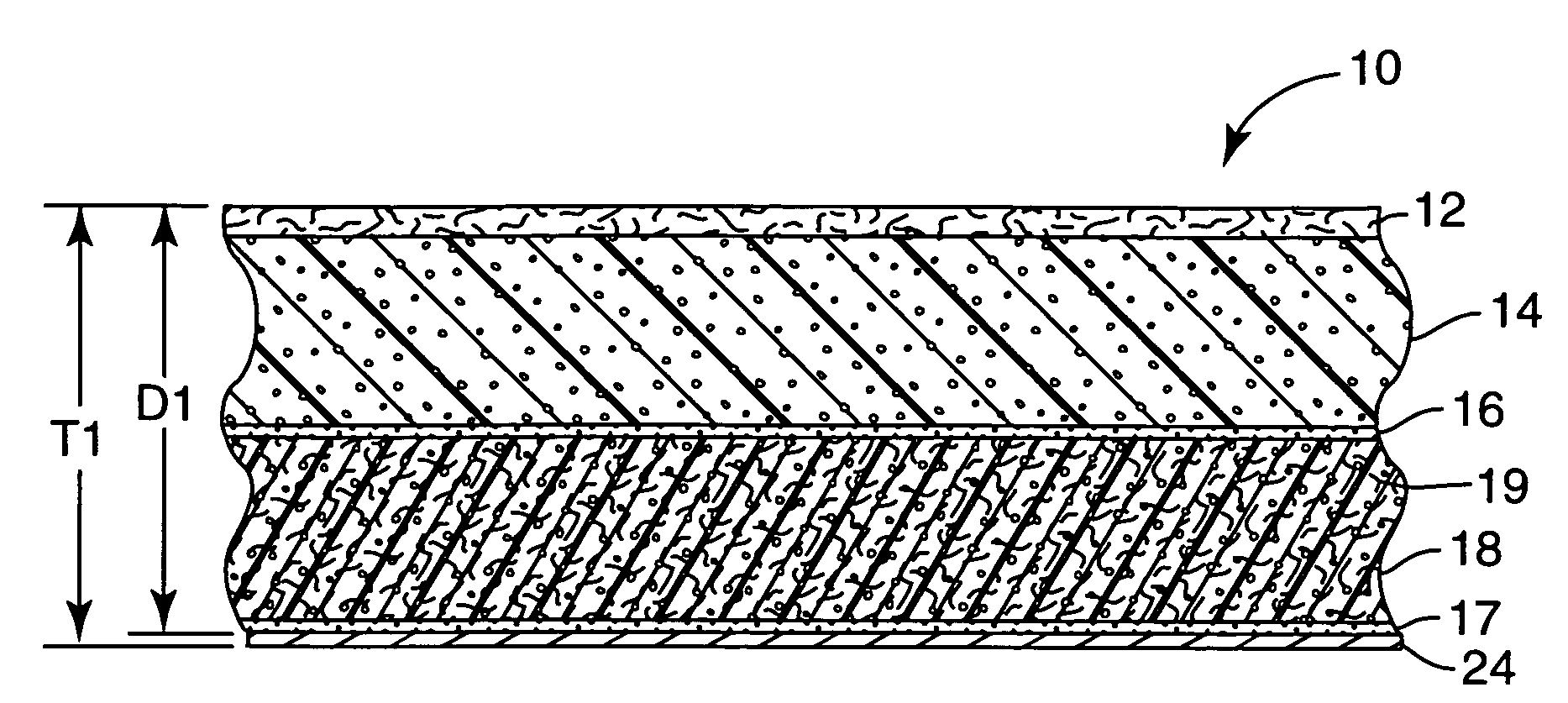
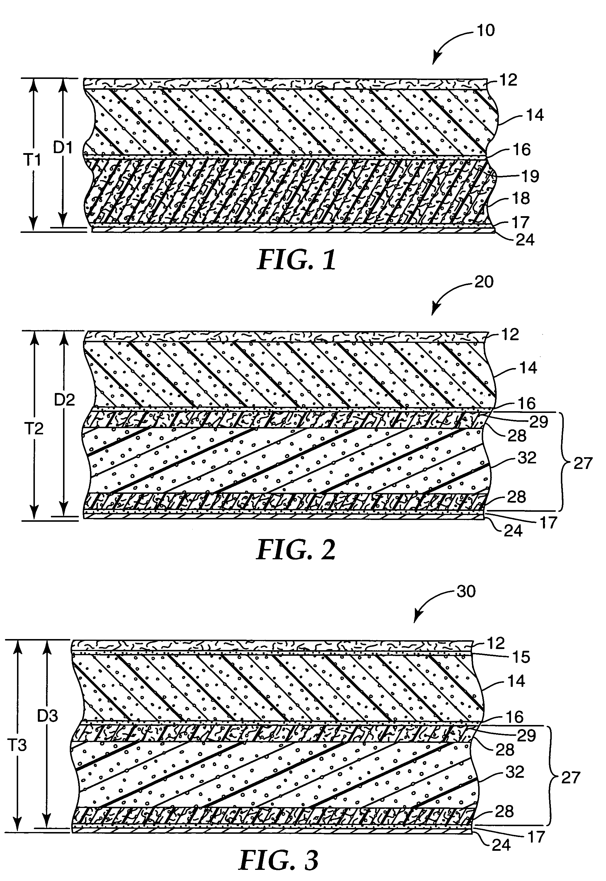
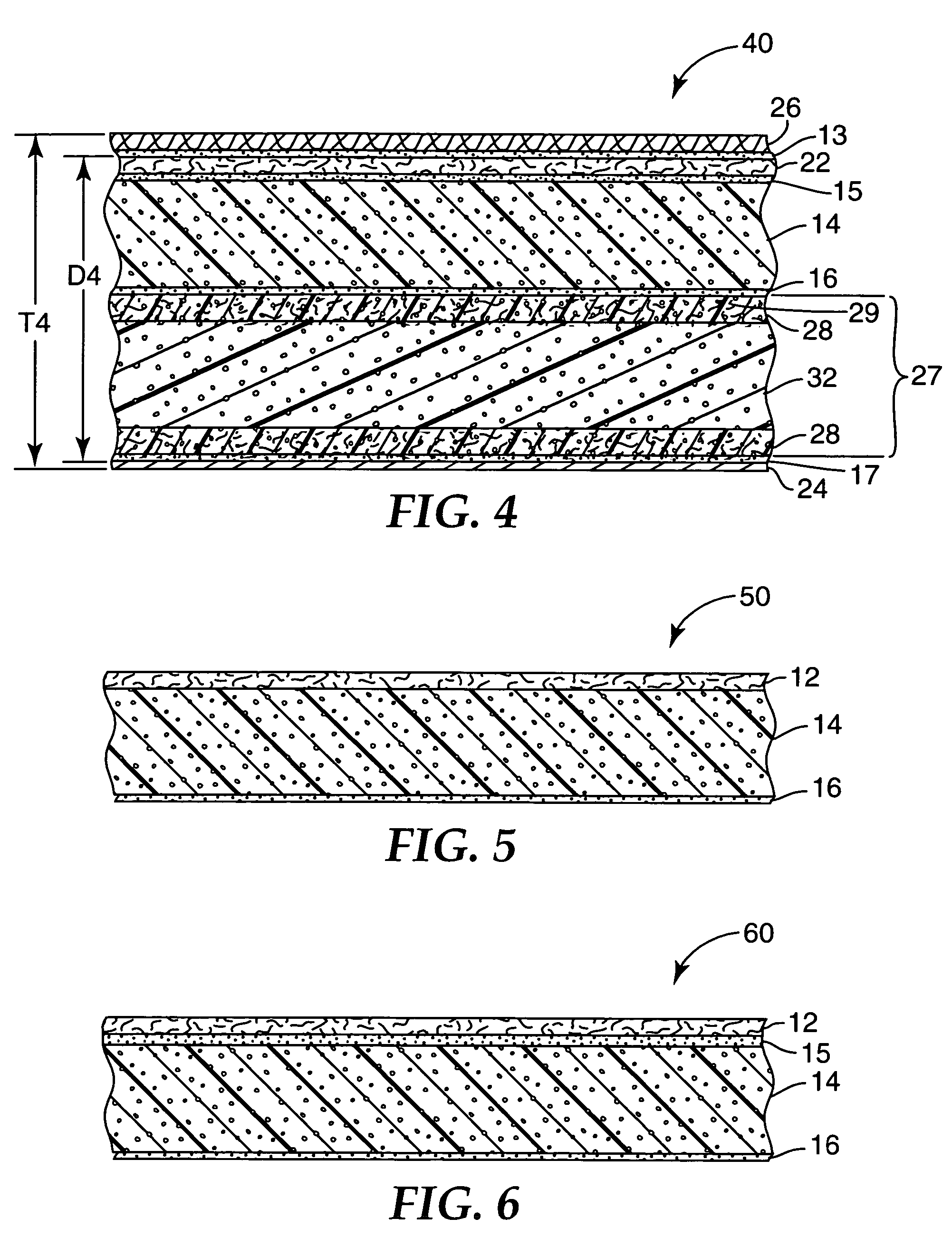
[0005]The design of headliners and other sound absorptive multilayer composites requires balancing a number of sometimes competing factors including thickness, weight, acoustic performance and manufacturability. Acoustic performance can be greatly assisted by placing a semipermeable airflow-resistive membrane at or very close to the headliner's passenger or occupant side and an air-impermeable film at or very close to the headliner's roof or vehicle side. In many current headliner designs this has not been done, and consequently the designs may have suboptimal acoustic performance. By rearranging the layers in some headliner designs or by adding a properly chosen and properly positioned semipermeable airflow-resistive membrane, a properly chosen and properly positioned air-impermeable barrier, or a properly chosen and properly positioned open cell foam layer, we have obtained significant improvements in acoustic performance. Doing so may impose no or a very low additional thickness or weight penalty, and may audibly reduce vehicular interior noise levels.

Problems solved by technology

In many current headliner designs this has not been done, and consequently the designs may have suboptimal acoustic performance.
Doing so may impose no or a very low additional thickness or weight penalty, and may audibly reduce vehicular interior noise levels.

Method used


Image

  • Sound absorptive multilayer composite
  • Sound absorptive multilayer composite
  • Sound absorptive multilayer composite

Examples


example 2

[0059]The Example 1 composite facing fabric layer was lightly coated with another misted layer of spray adhesive and covered with a second layer of the semipermeable airflow-resistive membrane employed in Example 1. Acoustically, the result was like using a single, more airflow-resistive membrane. The resulting sound absorptive multilayer composite had a structure like composite 80 shown in FIG. 8. Adhesive layer 9 had a negligible thickness. The composite had an 11.7 mm cavity depth and an 12.3 mm total composite thickness, or a 95% ratio of cavity depth to total composite thickness. This composite was identified as Example 2 and evaluated for sound absorption at normal incidence using the method of Example 1. The sound absorption results are shown as Curve 2 in FIG. 9, and demonstrate that a further improvement in sound absorption could be obtained at lower frequencies by using a more airflow-resistive membrane.

example 3

[0060]A composite was prepared by swapping the locations of the semipermeable airflow-resistive membrane (membrane 12 in FIG. 7) and the open cell foam layer (foam 14 in FIG. 7) in the Example 1 composite so that the semipermeable airflow-resistive membrane was buried beneath the foam layer and thus further from the occupant side. A light mist coat of spray adhesive was used to reassemble the layers. The resulting composite was evaluated for sound absorption at normal incidence using the method of Example 1. This composite had a lower sound absorption coefficient (viz., poorer performance) than the Example 1 composite at all measured frequencies. The results are shown below in Table 1:

[0061]

TABLE 1Absorption Coefficient,Absorption Coefficient,Composite with MembraneFrequency, HzExample 1 Compositeand Foam Layers Reversed1000.020.0121250.020.0021600.040.0312000.060.0422500.080.0583150.1 0.0714000.120.0925000.160.1246300.2 0.1758000.270.2581k0.350.33 1.25k0.440.3831.6k0.520.4212k0.6 0...

example 4

[0063]A second sample of the European luxury sport utility vehicle automotive headliner evaluated in Comparison Example M was obtained from the vehicle manufacturer. The entire facing fabric layer was carefully removed, measured to determine that it had an airflow resistance well below 100 mks Rayls, and discarded. The exposed open cell foam layer was lightly coated with a misted layer of spray adhesive and covered with the semipermeable airflow-resistive membrane employed in Example 1. A hot air gun was used to remove wrinkles. The completed headliner was identified as Example 4 and shipped back to the vehicle manufacturer for an in-vehicle noise comparison to the original equipment headliner. The noise comparison test was performed on a smooth surface track at 112 kilometers per hour, using a microphone placed near the driver's right ear. The results are shown in FIG. 11 as a plot of sound pressure level (SPL) vs. frequency. Curve M shows the original equipment noise level and cur...


PUM

PropertyMeasurementUnit
thicknessaaaaaaaaaa
total thicknessaaaaaaaaaa

Abstract

A sound absorptive multilayer composite having an air-impermeable barrier, an air-permeable reinforcing core having an airflow resistance of at least about 100 mks Rayls and a thickness at least about ⅓ the final composite thickness, an air-permeable open cell foam or fibrous pad having an airflow resistance less than about 2000 mks Rayls and a thickness at least about 1 / 10 the final composite thickness and a semipermeable airflow-resistive membrane having an airflow resistance of about 500 to about 4000 mks Rayls can provide improved acoustic performance. For example, existing vehicular headliner designs may be improved by adding a properly chosen and properly positioned semipermeable airflow-resistive membrane, a properly chosen and properly positioned air-impermeable barrier, or a properly chosen and properly positioned open cell foam layer.

Description

CROSS-REFERENCE TO RELATED APPLICATION[0001]This application is a continuation-in-part of copending U.S. patent application Ser. No. 10 / 335,752 filed Jan. 2, 2003, entitled ACOUSTIC WEB, the entire disclosure of which is incorporated by reference herein.FIELD OF THE INVENTION[0002]This invention relates to sound absorptive multilayer composites, and to precursor components and methods for the preparation or such composites.BACKGROUND[0003]Multilayer composite articles are sometimes used to absorb sound and thereby reduce noise levels in nearby spaces. For example, sound absorptive multilayer composites may be employed in headliners, trunk liners, hood liners, dash mats, interior panels, carpeting and other porous decorative or functional vehicular facing materials to provide enhanced noise reduction in a vehicle interior.[0004]References relating to acoustic insulation, vehicular facings or noise reduction include U.S. Pat. Nos. 5,459,291, 5,536,556, 5,549,776, 5,565,259, 5,824,973,...

Claims


Application Information

Patent Timeline
Patent Type & Authority Patents(United States)
IPC IPC(8): B32B37/00B01D53/22B01D67/00B01D69/02B32B5/18B32B5/32B32B7/022B32B27/12B60R13/08G10K11/162
CPCB32B5/02B32B5/18B32B5/24B32B5/245B32B5/32B32B7/02B32B7/12B32B27/065B32B27/12B32B27/32B60R13/011B60R13/02B60R13/0256B60R13/0815B60R13/083B60R13/0838G10K11/162G10K11/168B01D53/228B01D67/0088B01D67/009B01D69/02B32B5/04Y10T156/1002B32B2255/02B32B2262/0276B32B2262/101B32B2262/12B32B2262/14B32B2266/025B32B2266/0278B32B2266/06B32B2307/102B32B2307/724B32B2307/7242B32B2605/08B01D2325/26B32B7/022B60R13/08
Inventor THOMPSON, JR., DELTON R.LIU, XIAOHE
Owner 3M INNOVATIVE PROPERTIES CO
Learn More