
Auxiliary eyewear assembly with micromagnetic attachment

a technology of auxiliary lens and eyewear, applied in the field of eyewear, can solve the problems of unattractiveness, over-complicated, and inability to accommodate anyone other than farsighted individuals, and achieve the effects of preventing disassociation of auxiliary lens assembly, improving peripheral vision and appearance, and less expensive manufacturing

Inactive Publication Date: 2008-01-22
ASPEX EYEWEAR +1
View PDF16 Cites 22 Cited by
  • Summary
  • Abstract
  • Description
  • Claims
  • Application Information

AI Technical Summary

Benefits of technology

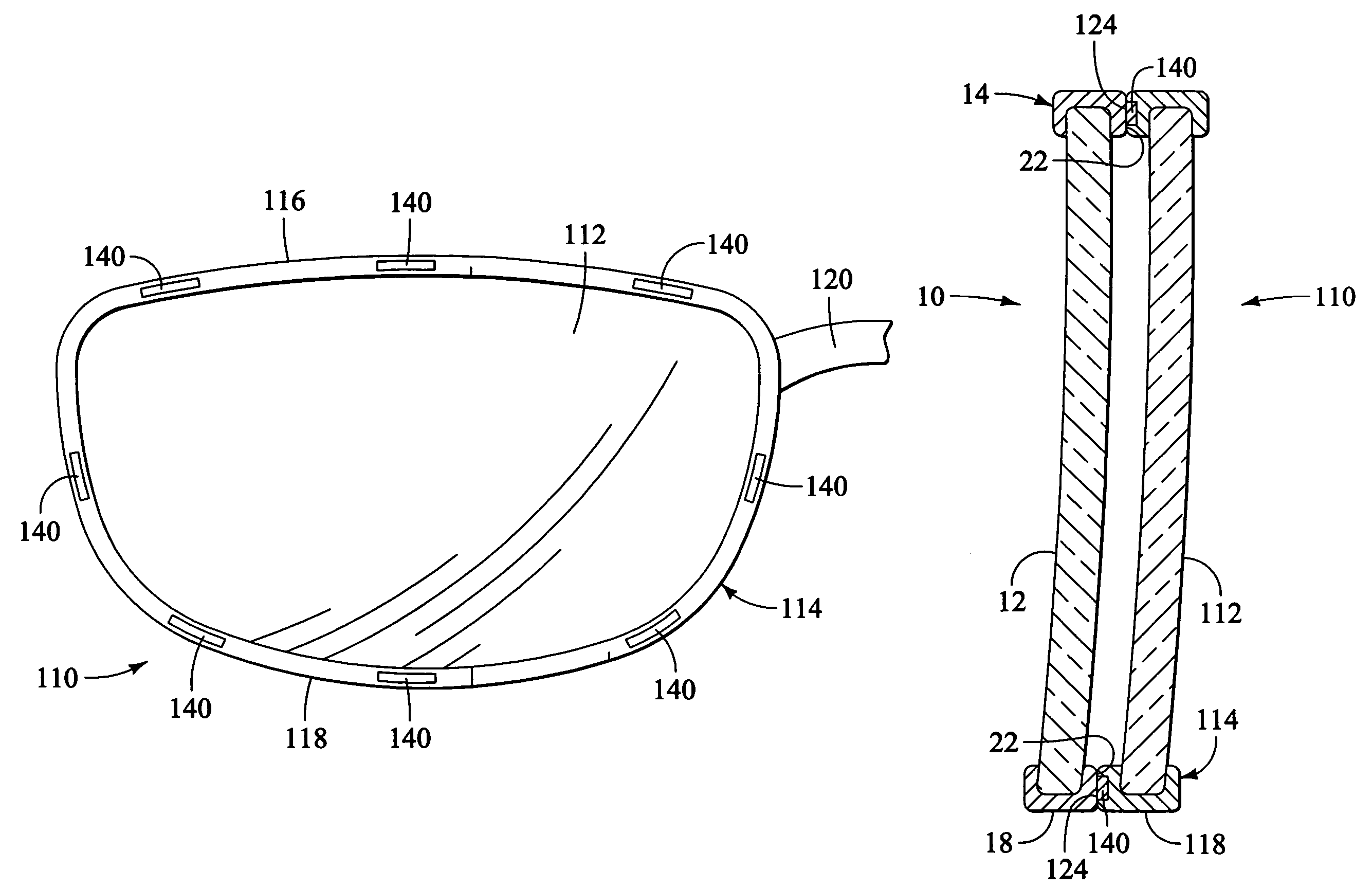
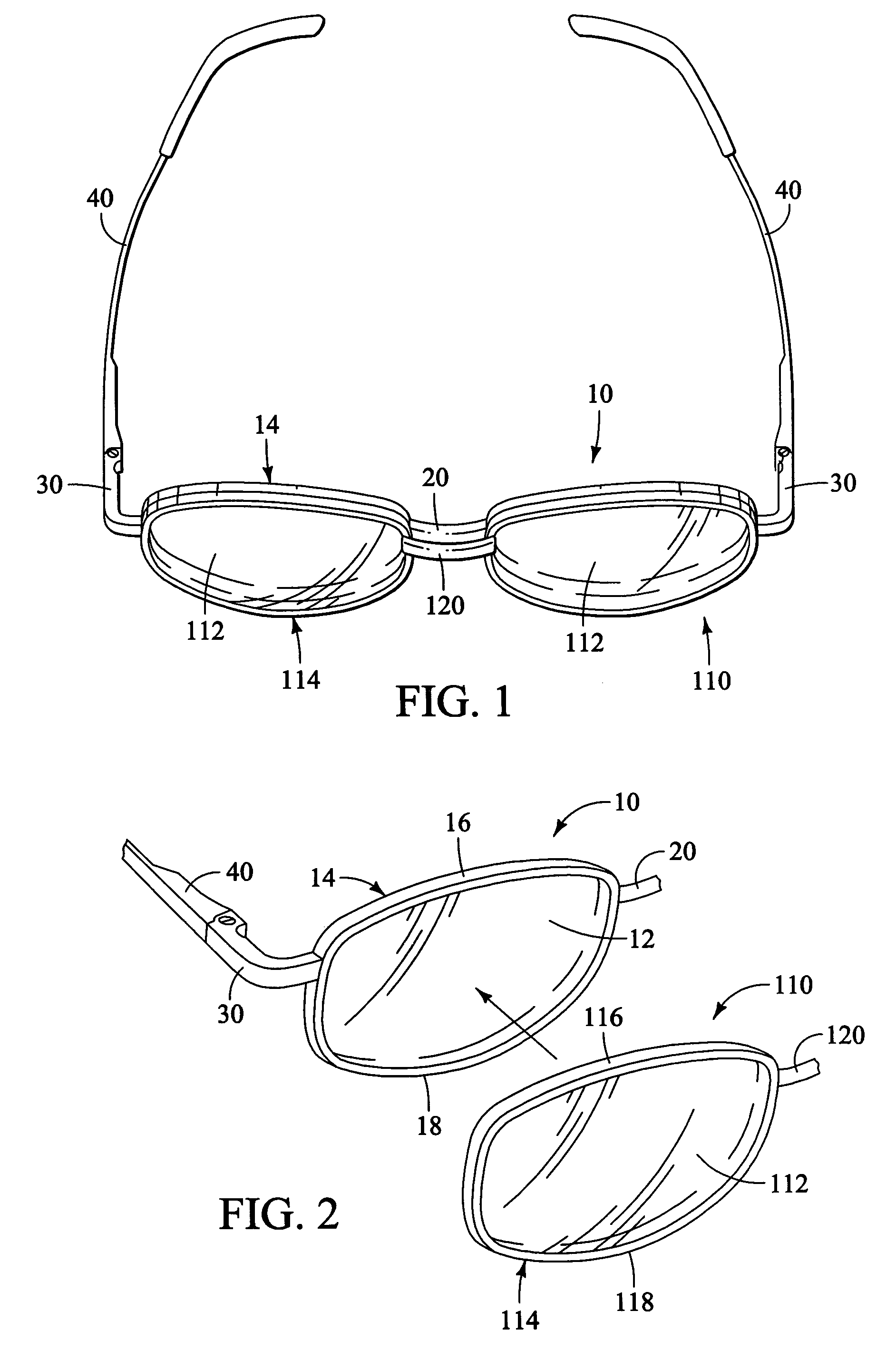
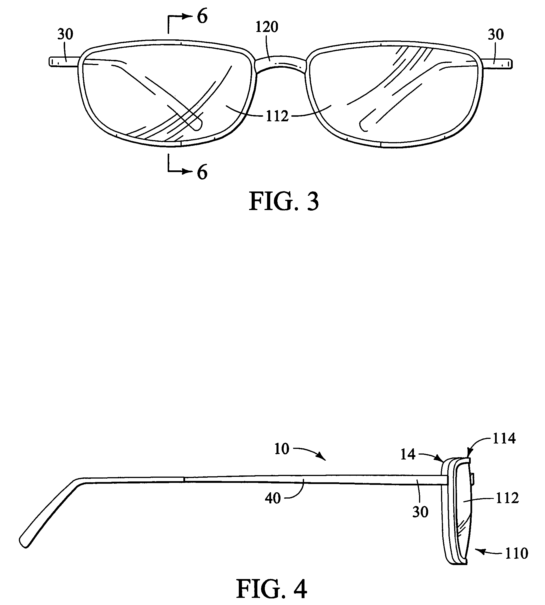
"The present invention is an eyewear system that allows for the use of wider lenses to improve peripheral vision and appearance. It does not require mechanical interlocking engages to prevent disassociation of the auxiliary lens assembly from the primary lens assembly. The invention is also less expensive to manufacture, provides a simplified and improved alignment between the auxiliary lens assembly and the primary lens assembly, and uses a magnetic system that does not require electroplating or other coating. The invention is aesthetically appealing and light-weight. The primary lens assembly includes a primary frame made of magnetically attractable material and the auxiliary lens assembly includes a frame made of magnetically attractable material. The frames are placed in close alignment to create a secure attachment between them. The invention allows for the use of different types of lenses, such as corrective lenses or light transmission reducing lenses."

Problems solved by technology

A significant disadvantage of this design is that it is unattractive, overly complicated, impossible to segregate from the primary frame, and does not permit or accommodate anyone other than farsighted individuals.
A significant disadvantage of this design is that it is unattractive, overly complicated, and resists easy and immediate removal of the auxiliary lens assembly.
As stated, these and other mechanically clipped on devices for holding auxiliary lenses are cumbersome and unattractive.
The magnetic engagements themselves are insufficiently strong to retain the auxiliary frame assembly.
They do not enjoy the advantages of the early flip-up designs, which permitted quick movement of the auxiliary assembly out of alignment with the primary assembly without separating them from the primary assembly.
A significant disadvantage of this design is that it is unstable, relying on tenuous repositioning and magnetic forces alone to align and support the auxiliary assembly to the primary assembly.
Another significant disadvantage of this design is that it causes the auxiliary frame to be positioned into the forehead of the wearer, making raising the auxiliary assembly fully perpendicular to the primary assembly impractical.
One disadvantage of this design is that it fails to limit the rotation of the auxiliary lens assembly.
Another disadvantage is that it is aesthetically unappealing, due in part to the long shelter arm requirement.
Another disadvantage is that it relies on a bridge magnet or bride hook for stability.
Another disadvantage is that the device relies on magnetic force to pull the magnetic housing forward, over a rearward protruding lens locker, requiring the user to push the auxiliary frame awkwardly rearward, into the primary frame, to disengage the magnetic housing from over the lens locker.
Another disadvantage is that the device is complex and expensive to manufacture.
As a result, peripheral vision through the lens is limited.
This can give rise to both convenience and safety issues.
These processes increase the time required to effect the maneuver, and results in the increased time in which the direction in which the car is traveling at high speed is not visible.
Problems occur again when trying to back up a vehicle.
The resulting disadvantage is that the prior art design for primary and auxiliary lens assemblies involve delicate soldering of numerous extraneous parts which extend from the sides of the lens assemblies.
A disadvantage of this invention is that the magnetic band made of conventional magnet materials is bulky and heavy, and the entire assembly is overly complicated.
Also, band-like magnetic materials must be ductile enough to prevent breakage, and thus the compositions of the magnetic materials suitable for use is limited.
A disadvantage of this design is that the resulting eyeglass frame is relatively bulky and the discrete magnets made of conventional materials lack sufficient power and life to support the auxiliary lens assembly to the primary lens assembly.
The disadvantage of this design is in the manufacture cost and challenges associated with heat treating a thin metal frame, as well as the lack of strength and life of the magnetic field.
However, there are disadvantages associated with employing uniformly distributed magnetic materials throughout the auxiliary lens assembly.
In particular, the cost of metallurgy associated with the manufacture of uniformly distributing magnetic materials can be high.

Method used


Image

  • Auxiliary eyewear assembly with micromagnetic attachment
  • Auxiliary eyewear assembly with micromagnetic attachment
  • Auxiliary eyewear assembly with micromagnetic attachment

Examples


Embodiment Construction

[0052]In the following discussion, numerous specific details are set forth to provide a thorough understanding of the present invention. However, those skilled in the art will appreciate that the present invention may be practiced without such specific details. In other instances, well-known elements have been illustrated in schematic or block diagram form in order not to obscure the present invention in unnecessary detail.

[0053]The following description is presented to enable any person skilled in the art to make and use the invention, and is provided in the context of a particular application and its requirements. Various modifications to the disclosed embodiments will be readily apparent to those skilled in the art, and the general principles defined herein may be applied to other embodiments and applications without departing from the spirit and scope of the present invention. Thus, the present invention is not intended to be limited to the embodiments shown, but is to be accord...


PUM


Abstract

Primary and auxiliary lens assemblies are provided that allow a wearer easy usage with a reduced risk of misalignment or detachment through the use of micromagnets. Conventional magnetic auxiliary lens assemblies are difficult to manufacture and functionally limited due to the limitations of conventional magnets and the composition of the auxiliary frames. The improved lens assemblies disclosed herein instead employ high strength micromagnets advantageously aligned and embedded in the auxiliary lens frame to improve the ease and reliability of coupling to a primary frame, and to provide aesthetic and functional advantageous over the known art.

Description

CLAIM OF PRIORITY[0001]This application claims priority from U.S. Provisional Patent Application No. 60 / 627,451 entitled “AUXILIARY EYEWEAR ASSEMBLY WITH MICROMAGNETIC ATTACHMENT” filed on behalf of Greg Smith on Nov. 12, 2004, and is hereby incorporated by reference for all purposes.TECHNICAL FIELD OF INVENTION[0002]The present invention relates to eyewear and, in particular, to an eyewear assembly that incorporates an auxiliary lens assembly for removable attachment to a primary lens assembly. Still more specifically, the present invention relates to an auxiliary lens assembly configured for micromagnetic attachment to a primary lens assembly.BACKGROUND OF THE INVENTION[0003]It has long been desirable to have a removable auxiliary lens assembly attached to eyeglasses. Professional baseball players have used “flip-up” auxiliary lenses for more than four decades to protect their eyes from the sun, but to allow them unrestricted vision in the event the ball was hit in their vicinity....

Claims


Application Information

Patent Timeline
Patent Type & Authority Patents(United States)
IPC IPC(8): G02C9/00
CPCG02C9/00G02C2200/02
Inventor SMITH, GREG
Owner ASPEX EYEWEAR
Learn More