
Method for determining of the formation factor for a subterranean deposit from measurements on drilling waste removed therefrom

a technology of subterranean deposits and measurement methods, applied in the field of methods for determining the formation factor of subterranean deposits from measurements on drilling waste removed therefrom, can solve the problems of difficult measurement results, high cost of methods, and relatively long measurement tim

Inactive Publication Date: 2008-01-15
INST FR DU PETROLE
View PDF16 Cites 10 Cited by
  • Summary
  • Abstract
  • Description
  • Claims
  • Application Information

AI Technical Summary

Benefits of technology

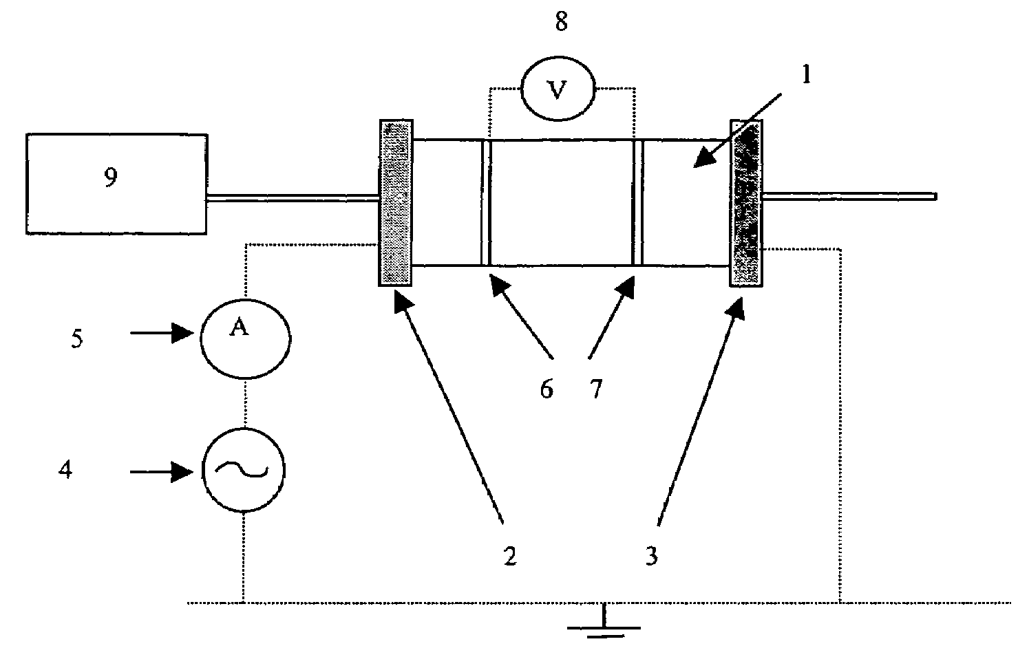
The invention is a method for quickly and easily determining the formation factor of an underground zone from drill cuttings taken to the wellbore surface. The method involves using a device that includes a cell for containing cuttings and electrodes connected to a device for measuring the conductivity of the cell content. The method involves at least the following stages: cleaning the cuttings, filling the cell with a first electrolyte solution, measuring the global electrical conductivity of the cell, discharging the first electrolyte solution, filling the cell with a second electrolyte solution, and determining the global electrical conductivity of the cell containing the cuttings and the second electrolyte solution. The invention also relates to a device for implementing the method. The technical effect of the invention is to provide a simple and fast way to determine the formation factor of an underground zone from drill cuttings.

Problems solved by technology

These methods are expensive because of the cost of the coring operation and of the measurement itself, and the results are available only several months after drilling.
However, these techniques are very restricting on an experimental plane and the measurements relatively long to obtain.

Method used


Image

  • Method for determining of the formation factor for a subterranean deposit from measurements on drilling waste removed therefrom
  • Method for determining of the formation factor for a subterranean deposit from measurements on drilling waste removed therefrom
  • Method for determining of the formation factor for a subterranean deposit from measurements on drilling waste removed therefrom

Examples


Embodiment Construction

[0037]The method according to the invention, intended for fast determination of the FF from drill cuttings, is based on the acquisition of experimental data obtained by measuring the conductivity of the cuttings under various conditions. When measuring the electrical conductivity of a cell containing rock fragments, the conductivity depends on the conductivity of the rock fragments and of the liquid contained between the fragments. The method provided allows to interpret the experimental measurements in terms of FF using theoretical models. Two application instances are provided. They show the very good agreement between the FF values obtained from cores and the FF values obtained from fragments of these cores over a wide FF range.

[0038]The invention provides a method and a device allowing fast and rigorous calculation of the formation factor by means, among other things, of conductivity measurements performed with two conducting liquids that can be miscible.

[0039]According to an em...


PUM

PropertyMeasurementUnit
total volumeaaaaaaaaaa
surface areaaaaaaaaaaa
conductivityaaaaaaaaaa

Abstract

Method and device for determining the formation factor of underground zones from drill cuttings. The device comprises a cell (1) associated with a device for measuring the electrical conductivity of the cell with the content thereof. The cell containing the drill cuttings is filled with a first electrolyte solution (A) of known conductivity (σA). After saturation of the drill cuttings by first solution (A), the global electrical conductivity (σ*A) of the cell with the content thereof is determined. After discharging first solution (A), the cell containing the drill cuttings is filled with a second electrolyte solution (B) of known conductivity (σB), and the global electrical conductivity (σ*B) of the cell containing the second solution and the cuttings saturated with the first solution is determined. The cuttings formation factor (FF) is deduced therefrom by combination of the measurements.

Description

FIELD OF THE INVENTION[0001]The present invention relates to a method and to a device for determining the formation factor of underground zones from rock cuttings taken to the surface during well drilling operations through underground reservoirs.[0002]In the sphere of petrophysical characterization, there is a very important datum which conditions the interpretation of electric logs for evaluation of the water saturation in reservoirs: the factor referred to as Formation Factor (FF in short hereafter), which is defined as the ratio of the conductivity of a conducting liquid alone (σw) to the conductivity of the porous medium saturated with this conducting liquid (σ0), i.e.:[0003]FF=σwσ0.[0004]Brine or another equivalent conducting liquid is preferably used as the conducting liquid.[0005]Knowledge of this formation factor allows operating companies to obtain a first petrophysical characterization of a reservoir shortly after drilling the well and, consequently, good evaluation of th...

Claims


Application Information

Patent Timeline
Patent Type & Authority Patents(United States)
IPC IPC(8): G01V3/00G01N15/08G01N33/24
CPCG01N33/241
Inventor LENORMAND, ROLANDEGERMANN, PATRICKBEHOT, JO LLE
Owner INST FR DU PETROLE
Learn More