
Fluid exchange in a chamber on a microscope slide

a technology of microscope slide and chamber, which is applied in the field of instruments, can solve the problem that the chamber is normally not accessible to the outside environment, and achieve the effect of preventing evaporation

Inactive Publication Date: 2008-01-15
DAKOAS
View PDF47 Cites 106 Cited by
  • Summary
  • Abstract
  • Description
  • Claims
  • Application Information

AI Technical Summary

Benefits of technology

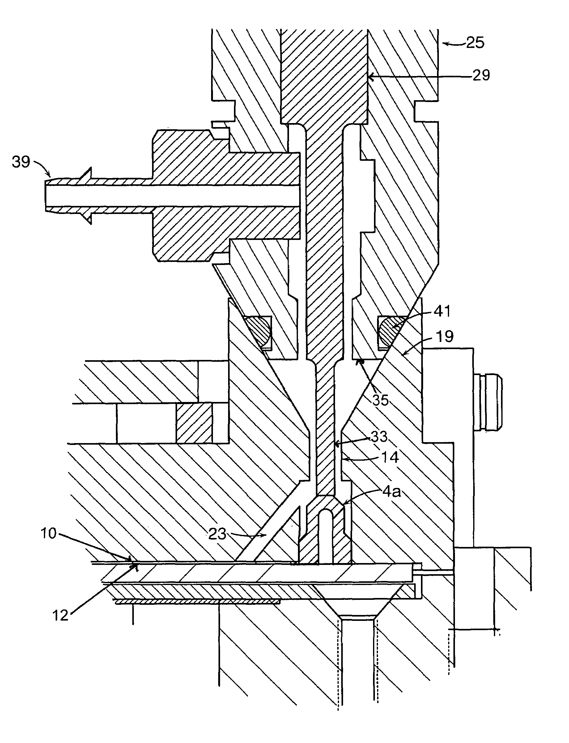
[0018]In embodiments of the present invention, a fluid handling apparatus is capable of spreading small amounts of liquid reagent over a flat surface, such as a microscope glass slide. The reagent may be sealed within a confined cavity, or “chamber”, so as to prevent evaporation even with heating of small amounts of reagent during an incubation period. One surface of this chamber is the flat slide surface. The remaining surfaces are formed by a cell. The cell is preferably a plastic disposable part that fits on top of the slide, over the area containing the tissue, biologic cells, or array mounted on the glass slide. The cell forms a fluid seal to the surface of the glass by means of a gasket. The gasket is mounted in a recess on the face of the cell that mates with the glass slide.
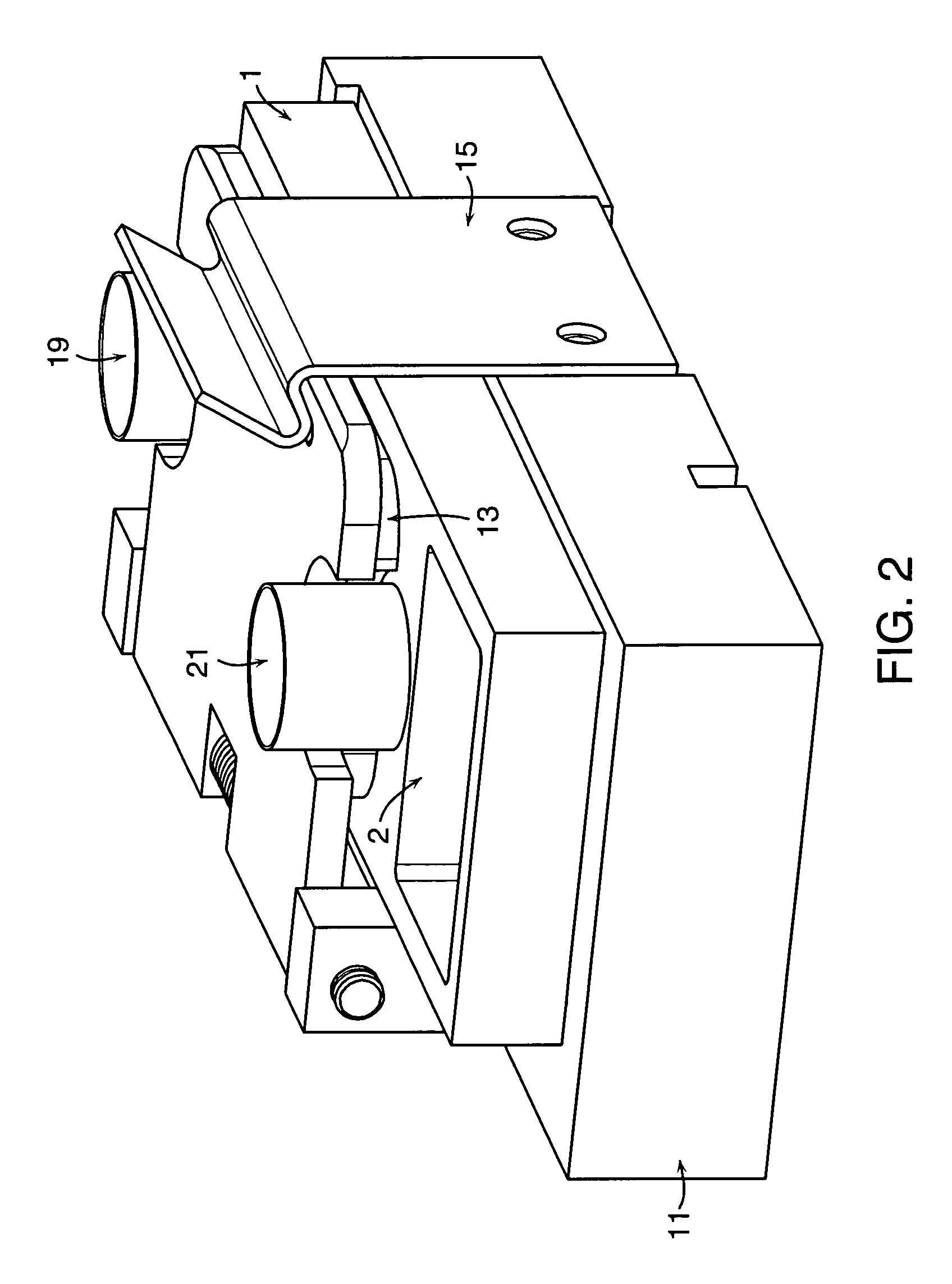
[0019]Each cell has two fluid ports. These ports are in fluid communication with the chamber. Therefore, when liquid reagent is inserted into a fluid port, it can travel into the chamber and contact the biologic sample or array mounted on the glass surface. The fluid ports on a cell are preferably positioned on opposite ends of the cell. This allows for liquid reagent or wash solution to flow in one fluid port, fill the chamber, and then exit the other fluid port at the other end of the cell. Each fluid port has a valve occluding the orifice that is normally closed. Consequently, the chamber is sealed. Unless the valves are opened, the chamber is normally not accessible to the outside environment. Liquid reagents or wash solutions are only added or removed by opening one or both of the valves associated with the fluid ports. The fact that the fluid ports are normally sealed by valves helps prevent evaporation.

Problems solved by technology

Unless the valves are opened, the chamber is normally not accessible to the outside environment.

Method used


Image

  • Fluid exchange in a chamber on a microscope slide
  • Fluid exchange in a chamber on a microscope slide
  • Fluid exchange in a chamber on a microscope slide

Examples


Embodiment Construction

[0043]A description of preferred embodiments of the invention follows.

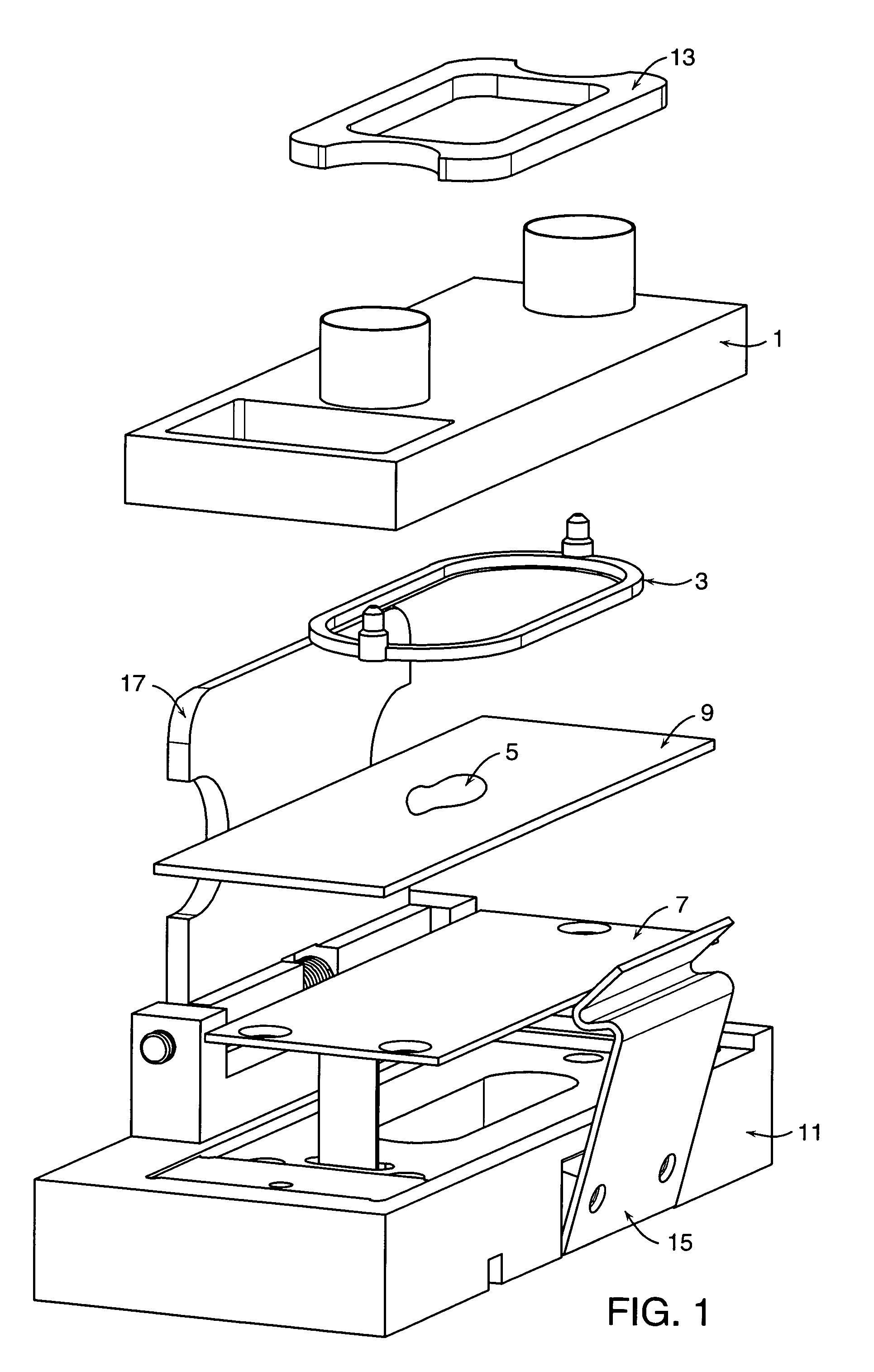
[0044]FIG. 1 shows an exploded view of a complete slide nest assembly. The assembly was designed as an “ISH cell”, “ISH” standing for in situ hybridization; however, it can be readily applied to other applications such as outlined in the Background. The ISH cell is comprised of a plastic cover 1 and a molded gasket 3. The gasket 3 fits into a groove (not shown) on the underside of the plastic cover 1. The ISH cell is positioned on top of a microscope slide 9 that bears a biologic sample 5 mounted on the surface of the slide. The microscope slide 9 rests on a heater plate 7. The heater plate is mounted, with screws (not shown), into a slide nest base 11. A resistive heating element (not shown) is attached to the underside of the heater plate 7. The heater plate thereby protects the electrical heater from any liquids that might spill. More importantly, the heater plate 7 diffuses the heat that emanates from the heat...


PUM


Abstract

A sample chamber is formed by a housing sealed against a microscope slide. The housing has fluid ports, including a well formed over at least one port. In a rinse station, rinse solution is drawn from a reservoir through the chamber to a waste reservoir. At a fill station, an aliquot of reagent already placed in the well is driven into the chamber. The reagent may be driven into the chamber by first drawing a vacuum on the chamber through the aliquot of reagent and then releasing the reagent to be drawn into the chamber by the vacuum.

Description

RELATED APPLICATIONS[0001]This application is a Divisional of U.S. application Ser. No. 09 / 549,414, filed Apr. 14, 2000 now U.S. Pat. No. 6,673,620, which claims the benefit of U.S. Provisional Application No. 60 / 130,171, filed Apr. 20, 1999, the entire teachings of which are incorporated herein by reference.GOVERNMENT SUPPORT[0002]The invention was supported, in whole or in part, by NIH grant 1R43CA84686-01 from Public Health Service. The Government has certain rights in the invention.BACKGROUND OF THE INVENTION[0003]This invention relates to an instrument that is capable of performing incubations of small volumes of reagents on the surface of a microscope slide. A variety of assays are typically carried out on the surface of a microscope slide. These assays generally aim to determine if a suspected analyte is present in a patient biopsy. They include: (1) in situ hybridization, for the detection of nucleic acid targets in a tissue or cell sample, (2) immunohistochemistry, for the ...

Claims


Application Information

Patent Timeline
IPC IPC(8): B01L1/00G01N35/10B01L3/00G01N1/31G02B21/26G02B21/34
CPCB01L3/502G01N1/312G01N35/00029G02B21/26G02B21/34Y10T436/112499B01L2200/0642B01L2300/0822B01L2300/0877B01L2400/049G01N2035/00039G01N2035/0437G01N2035/1032Y10T436/25Y10T436/2575B01L2200/027
Inventor LOEFFLER, HERBERT H.BOGEN, STEVEN A.
Owner DAKOAS
Learn More