
Stereolithographic apparatus and method for manufacturing three-dimensional object

Inactive Publication Date: 2008-01-15
TEIJIN SEIKI CO LTD
View PDF8 Cites 48 Cited by
  • Summary
  • Abstract
  • Description
  • Claims
  • Application Information

AI Technical Summary

Benefits of technology

[0014]An object of the present invention is to solve the above disadvantages and provide stereolithographic apparatus and method for forming a three-dimensional object, which allow the so-called plane exposure by a simple configuration without using grid or the like and reduce the calorific value of the light source without decrease in the stereolithographic molding accuracy.
[0015]Another object of the present invention is to provide stereolithographic apparatus and method for forming a three-dimensional object, which allow a plane exposure without decrease in the stereolithographic molding accuracy by preventing photohardenable resin from being warped due to shrinkage on hardening.

Problems solved by technology

In this case, however, the system has a disadvantage that it needs much time to expose each resin layer to light in order to harden the resin layer.
In this case, therefore, there is a trouble in which the stereolithographic molding accuracy is lowered more remarkably in comparison with so-called linear exposure using a laser beam.
However, the amount of light might be reduced by about 10% if the grid is used, so that there is another problem that the hardening time will be increased by almost 10 times.
In this case however, working electric power will be increased, resulting in the increase in a running cost of the system.
In particular, otherwise, the shutter deforms with the heat of the light source, resulting in occurrence of some trouble such as a malfunction or the like.

Method used


Image

  • Stereolithographic apparatus and method for manufacturing three-dimensional object
  • Stereolithographic apparatus and method for manufacturing three-dimensional object
  • Stereolithographic apparatus and method for manufacturing three-dimensional object

Examples


Embodiment Construction

[0067]Preferred embodiments according to the present invention will be described with reference to the accompanying drawings.

[0068]In the following embodiments, optical stereolithographic apparatus and method for optically forming a three-dimensional object in a stereolithographic process by successively irradiating light (as a hardening-promoting medium) to each photohardenable resin layer in the form of a plane through a mask will be representatively described. However, the stereolithographic apparatus and method of the present invention are not limited to the optical stereolithographic apparatus and method. For example, the present invention may be applied to any wider-concept stereolithographic apparatus and method insofar as a three dimensional object is stepwise formed by using materials that are hardened (or softened, liquefied or gasified) when physical or chemical phase-shifting media (when hardenable resin is used, hardening-promoting media (stimuli) such as light, heat, p...


PUM

PropertyMeasurementUnit
Pressureaaaaaaaaaa
Shapeaaaaaaaaaa
Electric potential / voltageaaaaaaaaaa

Abstract

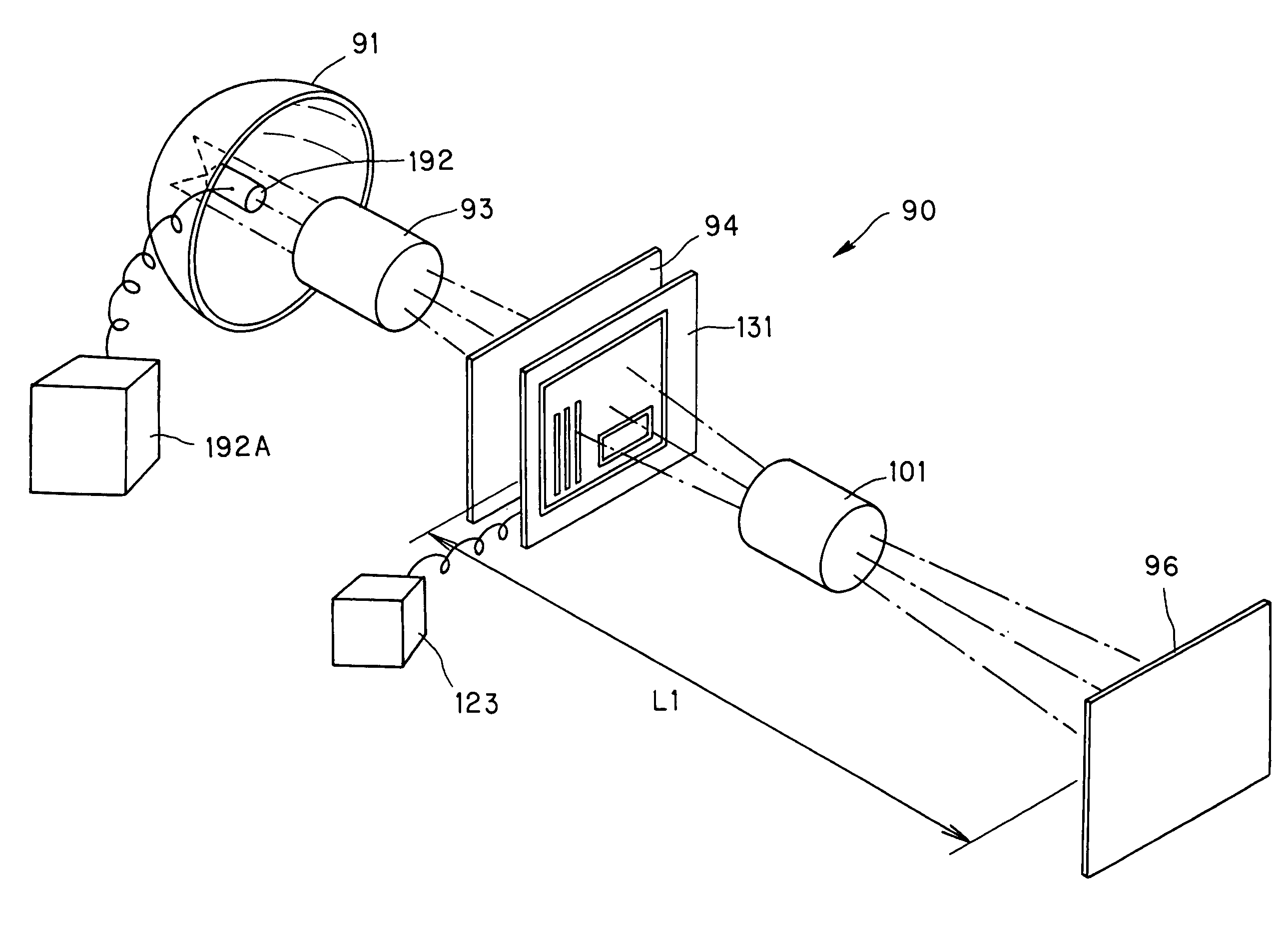
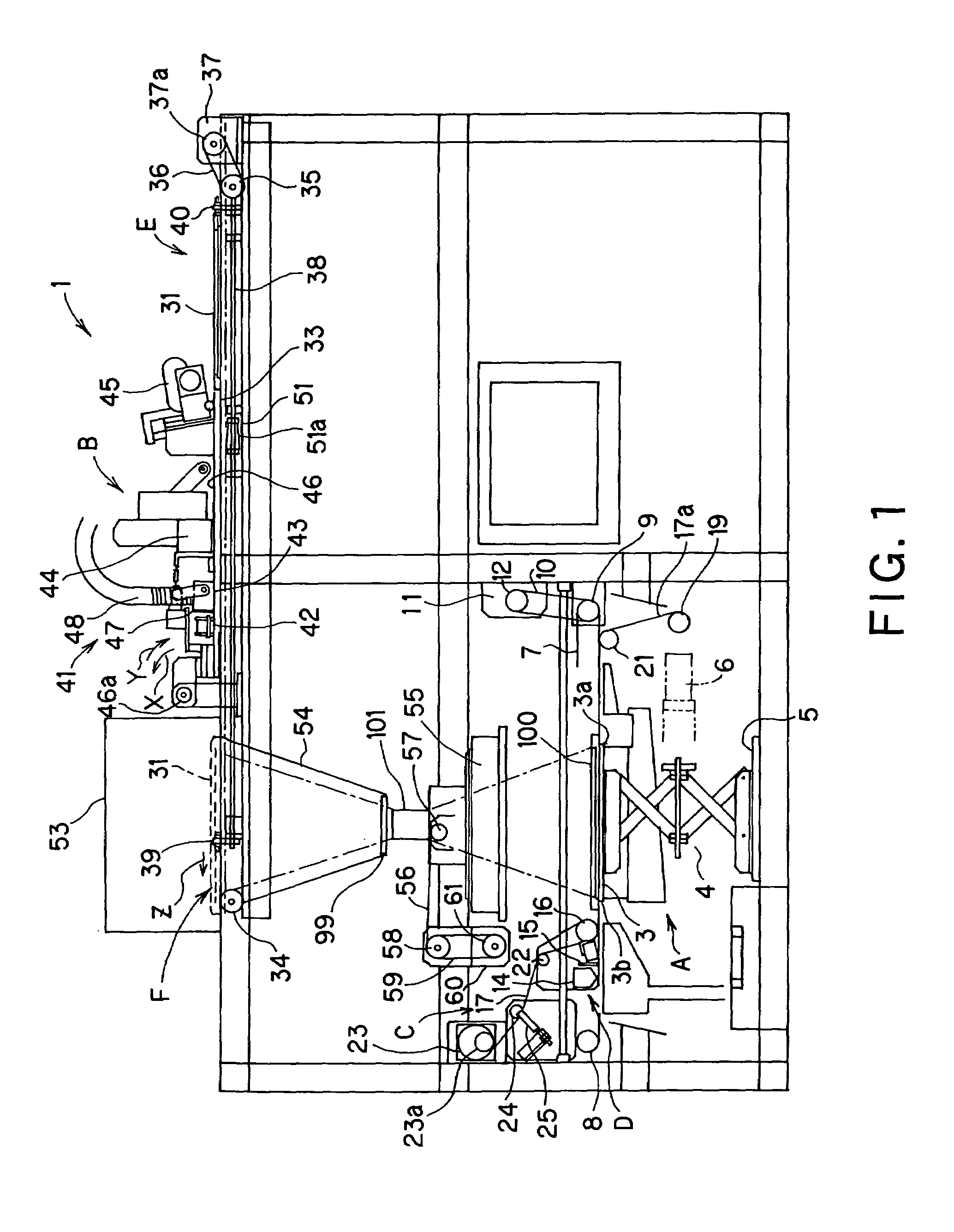
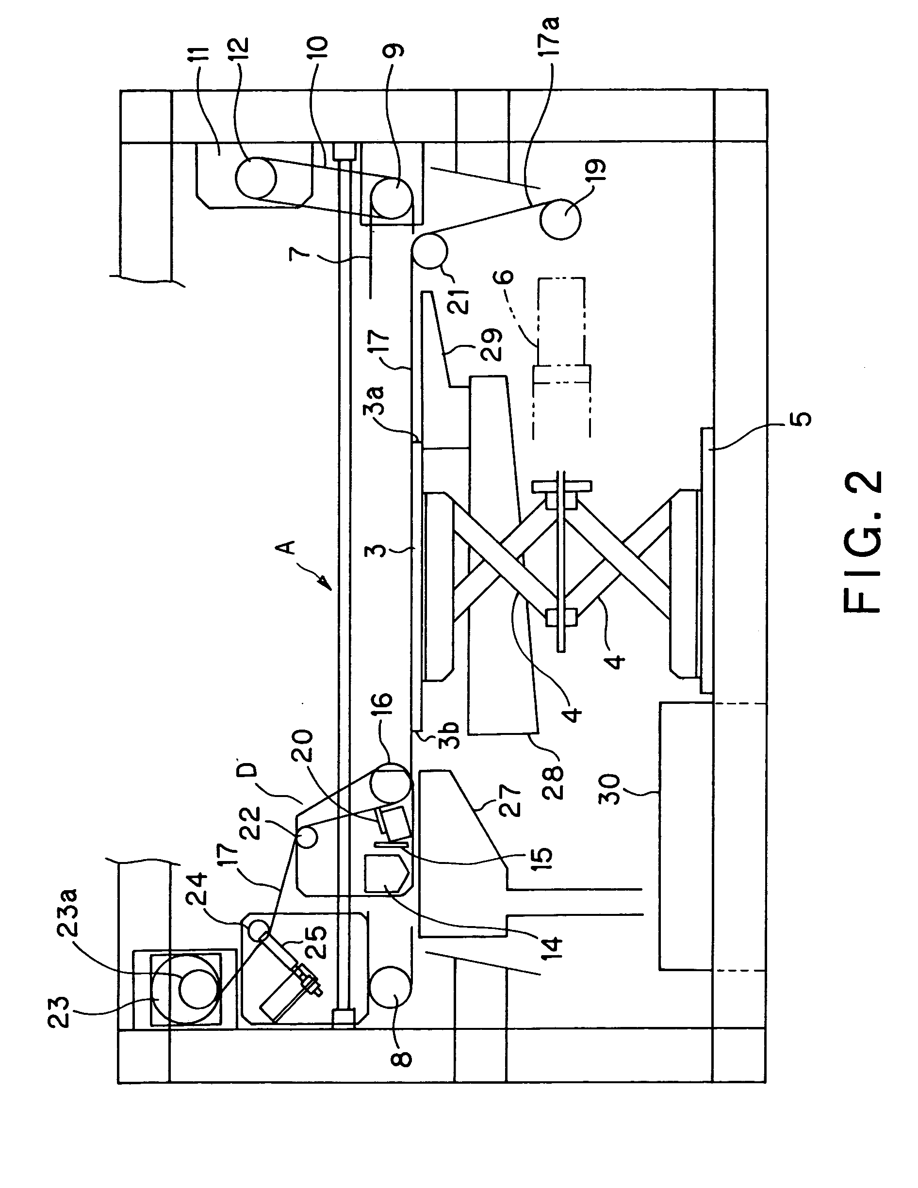
An optical stereolithographic apparatus performs optical stereolithography by preparing a mask on a light-transmissible member (31) on the basis of data for one layer with respect to optical stereolithography, exposing an unhardened resin layer (96) of photohardenable resin to light through the mask, and repeating an exposure operation. The optical stereolithographic apparatus has an optical system in which the light-transmissible member (31) and the unhardened resin layer (96) are spaced from each other at a predetermined distance, and the unhardened resin layer (96) of the photohardenable resin is subjected to a projection exposure through the mask.

Description

BACKGROUND OF THE INVENTION[0001]1. Field of the Invention[0002]The present invention relates to stereolithographic apparatus and method for preparing a mask having a mask pattern, exposing a hardenable resin or the like through the mask pattern to hardening-promoting medium such as light, heat, pressure, electromagnetic waves or the like in the form of a plane to harden the hardenable resin or the like, thereby forming a three-dimensional object.[0003]2. Description of the Related Art[0004]A stereolithographic system using a photolithographic apparatus for optically manufacturing a three-dimensional object (hereinafter the process of forming a three-dimensional object by using stereolithography will be referred to as “stereolithographic molding”) have been known in the art. The photolithographic apparatus generally includes a controller based on a three-dimensional computer-aided design (3D-CAD) for outputting stereolithographic data.[0005]In the photolithographic apparatus, photoh...

Claims


Application Information

Patent Timeline
IPC IPC(8): B29C35/08B29C67/00G03F7/20
CPCB29C67/007G03F7/2057G03F7/70416B29C64/129B33Y30/00B33Y10/00B33Y50/02
Inventor UENO, TAKAKUNI
Owner TEIJIN SEIKI CO LTD
Learn More