Device for compression crimping

Inactive Publication Date: 2008-01-15
SAURER GMBH & CO KG
View PDF20 Cites 1 Cited by
  • Summary
  • Abstract
  • Description
  • Claims
  • Application Information

AI Technical Summary

Benefits of technology

[0018]The use of ceramic coatings, or ceramic materials, also achieves a corrosion-resistant gas-permeable wall and decreased fallibility to fouling. In particular, deposits caused by preparation residue may be avoided. Even after a maintenance period, the same friction specifications are achieved when operating the device as prior to shutting down the facility.
[0021]In order to avoid wear inside the stuffer box on all sides contacting the yarn plug, an additional section with an enclosed chamber wall may be provided. In accordance with a preferred embodiment of this invention, the stuffer box includes an additional section with an enclosed chamber wall. The additional section is downstream from the section with the gas-permeable chamber wall. The enclosed chamber wall includes a contact surface comprised of a wear-resistant material on the inner side facing the yarn plug.
[0023]It was observed that when using a conveying nozzle with ceramic sides at least on parts of the surface contacting the yarn, that the yarn tension reduction in the conveying nozzle was reduced by the friction of the yarn on the side. In accordance with a preferred embodiment, the contact surfaces contacted by the yarn within the conveying nozzle are at least partially formed from a wear-resistant material in the form of a coating or a ceramic material. Thus, higher yarn tension can be achieved with the same conveying pressure, which results in higher operational uniformity of the texturizing process. On the other hand, yarn tension can be achieved with a lower pressure, whereby a lower conveying pressure results in less consumption of the conveying medium. The contact surface's wear-resistant material inside the conveying nozzle can be formed of coatings or ceramic base materials. Thus, the conveying nozzle can be preferentially manufactured entirely out of ceramics.
[0024]In another embodiment variant of the invention, the inlet of the yarn channel is formed by means of a guide insert in the conveying nozzle. The guide insert, which can be manufactured from a ceramic material or carry a coating on its surface, forms an intake channel as an extension of the yarn channel. Wear, in particular, at the yarn's entry into the conveying nozzle is thereby avoided. Using ceramic materials or ceramic coatings also enables a very low friction guidance of the yarn.
[0027]Since the conveying medium flowing into the yarn channel results in a sudden dynamic load for the yarn, in a preferred embodiment of the invention, the third guide insert includes an additional insert forming the inlet of the guide channel. The additional insert forms an intake channel arranged as an extension of the guide channel. Also, the additional insert is either manufactured from a ceramic material or coated on its surface. The third guide insert in the area of the air inlet includes the additional insert in the inlet of the guide channel. In this manner, yarn guidance is stabilized and disturbances affecting the yarn are avoided.

Problems solved by technology

Therefore, wear marks are unavoidable in prolonged operation, which results in a change in the braking action.
The texturizing process then fails.
On the other hand, as frictional forces increase, the yarn plug is no longer or no longer uniformly conveyed out of the stuffer box.
Non-uniform stuffer box crimping occurs when a stick-slip effect begins in the stuffer box.
These effects cannot be controlled with a dynamic medium opposing the conveying medium.

Method used


Image

  • Device for compression crimping
  • Device for compression crimping
  • Device for compression crimping

Examples


Embodiment Construction

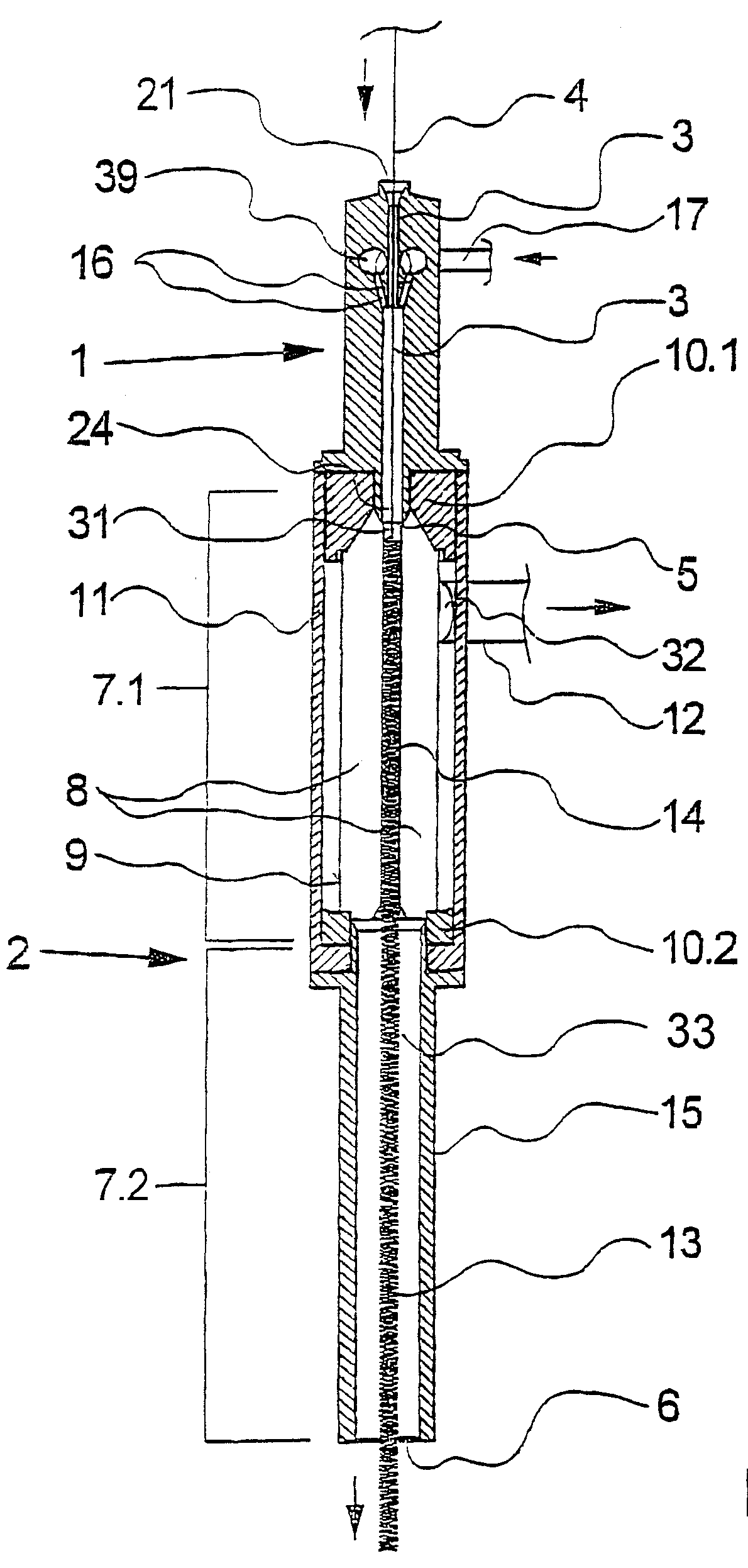
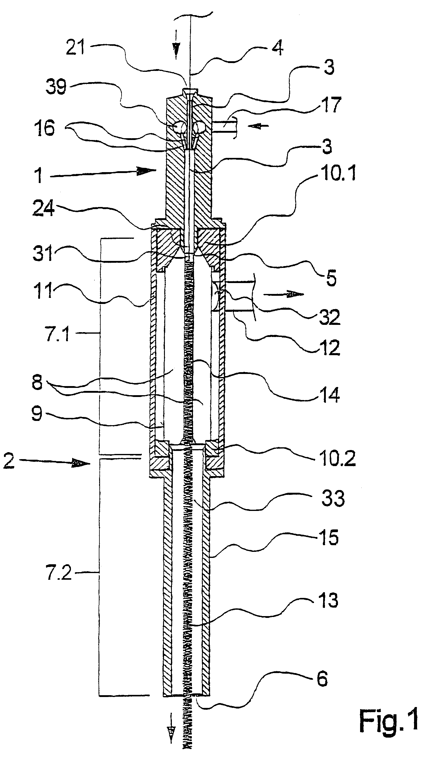
[0034]FIG. 1 schematically depicts a cross-sectional view of an initial embodiment of the device in accordance with this invention. The device consists of conveying nozzle 1 and stuffer box 2 arranged downstream from conveying nozzle 1. Conveying nozzle 1 comprises yarn channel 3 that forms inlet 21 on one end and outlet 24 on the opposite end. Conveying nozzle 1 is connected to a pressure source (not depicted) by means of feed line 17. Feed line 17 is connected to yarn channel 3 by air inlet 16 and pressure chamber 39. Air inlet 16 is formed by several boreholes that supply a conveying medium in yarn travel direction, marked by an arrow, to yarn channel 3. Yarn channel 3 merges into yarn channel 31 of stuffer box 2 by means of outlet 24.

[0035]Stuffer box 2 is formed by section 7.1 facing conveying nozzle 1 having yarn inlet 5, and section 7.2, arranged downstream from section 7.1, having a plug outlet 6. In section 7.1, plug channel 31 is formed by a gas-permeable chamber wall 8. G...


PUM

PropertyMeasurementUnit
Electrical resistanceaaaaaaaaaa
Permeabilityaaaaaaaaaa
Circumferenceaaaaaaaaaa

Abstract

The invention relates to a device for the compression crimping of a synthetic multifilament yarn, said device comprising a transport nozzle and a compression chamber. Said transport nozzle comprises a yarn channel by which means a yarn is guided to a compression chamber. Said compression chamber forms a section having a gas-permeable chamber wall, between a yarn inlet and an enmeshment outlet. According to the invention, the gas-permeable chamber wall comprises a friction surface consisting of material which is resistant to wear, on the inner side facing the yarn enmeshment. The constancy of the braking action produced by the friction on the yarn enmeshment can thus be significantly improved.

Description

[0001]The invention relates to a device for the stuffer box crimping of a synthetic multifilament yarn.[0002]The disclosure in German Patent Application 101 32 148.1 of Jul. 3, 2001 and PCT / EP02 / 07161 of Jun. 28, 2002 are incorporated herein by reference.BACKGROUND OF INVENTION[0003]An example of a device for the stuffer box crimping of a multifilament yarn is disclosed in EP 0 554 642 A1 and corresponding U.S. Pat. No. 5,351,374. The device comprises a conveying nozzle and a stuffer box arranged downstream from the conveying nozzle. The yarn is conveyed by means of the conveying nozzle into the stuffer box, compressed to a yarn plug and thereby stuffer box crimped. The conveying nozzle is loaded with a conveying medium, preferably a hot gas, which conveys the yarn within the yarn channel to the stuffer box. The yarn plug is formed inside the stuffer box. In doing so, the multifilament yarn deposits itself in loops on the surface of the yarn plug and is compressed by the conveying m...

Claims


Application Information

Patent Timeline
IPC IPC(8): D02G1/12
CPCD02G1/12D02G1/122
Inventor STUNDL, MATHIAS
Owner SAURER GMBH & CO KG
Why Eureka
Try Eureka